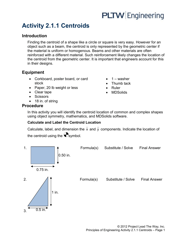
Activity 2.1.1 Centroids Introduction Finding the centroid of a shape like a circle or square is very easy. However for an object such as a beam, the centroid is only represented by the geometric center if the material is uniform or homogenous. Beams and other materials are often reinforced with a different material. Such reinforcement likely changes the location of the centroid from the geometric center. It is important that engineers account for this in their designs. Equipment Corkboard, poster board, or card stock Paper, 20 lb weight or less Clear tape Scissors 18 in. of string 1 – washer Thumb tack Ruler MDSolids Procedure In this activity you will identify the centroid location of common and complex shapes using object symmetry, mathematics, and MDSolids software. Calculate and Label the Centroid Location Calculate, label, and dimension the x and y components. Indicate the location of the centroid using the symbol. 1. Formula(s) Substitute / Solve Final Answer 0.50 in. 0.75 in. 2. Formula(s) Substitute / Solve Final Answer 1 in. 3. 0.5 in. © 2012 Project Lead The Way, Inc. Principles of Engineering Activity 2.1.1 Centroids – Page 1 yi Ai yi Ai Ai xi Ai 1. 2. 3. Total: xi 1. 2. 3. Total: y yiA i Ai x xiA i Ai Find the Centroid of a Beam Cross Section 1. Determine the overall dimensions of the poster board or card stock available to you. © 2012 Project Lead The Way, Inc. Principles of Engineering Activity 2.1.1 Centroids – Page 2 2. Choose a composite shape from below and determine the dimensions to be made out of one continuous piece of material. Make sure that the dimensions you choose are not larger than your piece of material. 3. Cut out the shape and identify three points on the perimeter of the shape. 4. Tie the washer to one end of the string. Tie a loop in the other end of the string to create a plumb bob. 5. Attach the shape to a bulletin board with the thumb tack through one of the previously identified points located on the perimeter of the shape. 6. Hang the plumb bob from the thumb tack. 7. Once the plumb bob stops swaying, mark a line on the shape along the path of the string. 8. Repeat the previous three steps using the two remaining points on the perimeter of the shape. 9. The centroid of the shape exists where the three lines intersect. Determine whether the shape will balance on your finger at the intersection. If it does, you have verified the centroid of the shape. 10. Measure the distance from the bottom of the shape to the centroid and then from the left edge of the shape to the centroid. Record those values below. © 2012 Project Lead The Way, Inc. Principles of Engineering Activity 2.1.1 Centroids – Page 3 Use MDSolids to Find the Centroid of Beam Cross Sections 1. Open MDSolids and choose Section Properties. 2. From the menu click on Flanged and choose the beam shape that you created. 3. Choose either mm or in. and enter the dimensions of your shape. Click Compute. 4. In the Cross Section Properties box, record the distance from the bottom. Choose Y axis Properties and record the distance from the left. 5. How closely did the measurements that you collected using the plumb bob match the measurements provided by MDSolids? What might cause error between the two? 6. Sketch and dimension two new flanged shapes below, then use MDSolids to locate the centroid on each shape. Label and dimension the centroid location on the drawn shapes. Conclusion 1. How does a crane operator’s knowledge of where the centroid is generally located for most uniform objects help them perform their job more safely? 2. In the construction industry, why are I beams generally used as support as opposed to solid rectangular beams? What might be an advantage of using a rectangular beam? © 2012 Project Lead The Way, Inc. Principles of Engineering Activity 2.1.1 Centroids – Page 4

