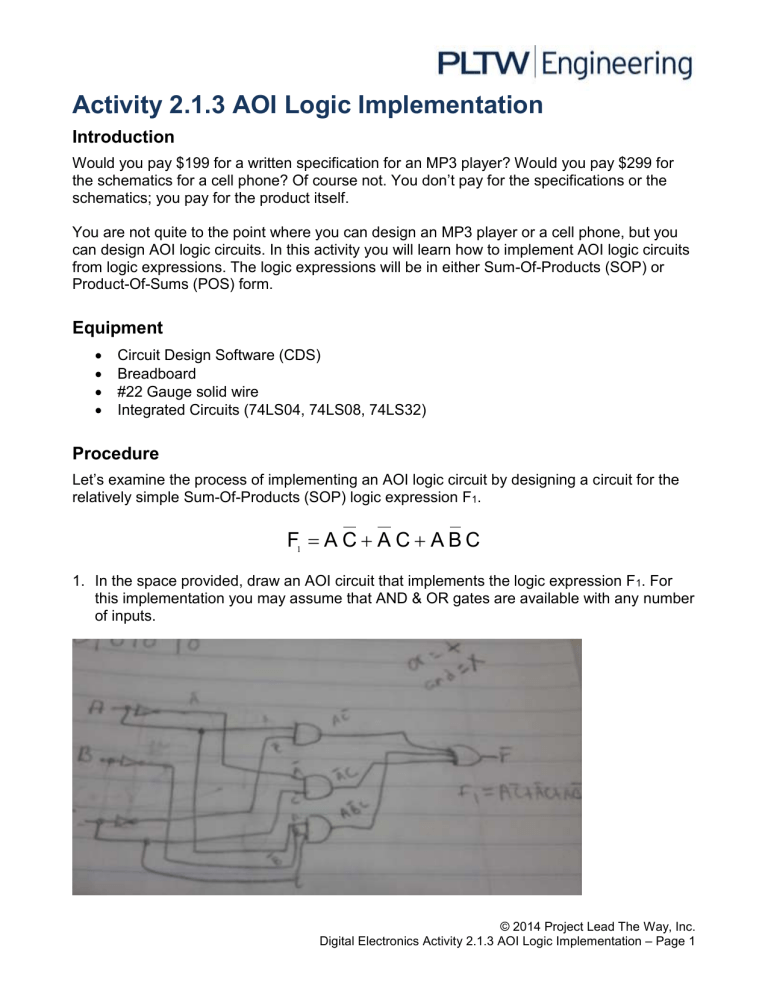
Activity 2.1.3 AOI Logic Implementation Introduction Would you pay $199 for a written specification for an MP3 player? Would you pay $299 for the schematics for a cell phone? Of course not. You don’t pay for the specifications or the schematics; you pay for the product itself. You are not quite to the point where you can design an MP3 player or a cell phone, but you can design AOI logic circuits. In this activity you will learn how to implement AOI logic circuits from logic expressions. The logic expressions will be in either Sum-Of-Products (SOP) or Product-Of-Sums (POS) form. Equipment Circuit Design Software (CDS) Breadboard #22 Gauge solid wire Integrated Circuits (74LS04, 74LS08, 74LS32) Procedure Let’s examine the process of implementing an AOI logic circuit by designing a circuit for the relatively simple Sum-Of-Products (SOP) logic expression F1. F1 A C A C A B C 1. In the space provided, draw an AOI circuit that implements the logic expression F 1. For this implementation you may assume that AND & OR gates are available with any number of inputs. © 2014 Project Lead The Way, Inc. Digital Electronics Activity 2.1.3 AOI Logic Implementation – Page 1 VCC 5V S1 U1 U4 NOT Key = A U2 S2 X1 AND2 2.5 V U7 U5 NOT OR3 AND2 Key = B U3 S3 U6 NOT AND3 Key = C GND F1 – I 2. Re-implement the circuit assuming that only 2-input AND gates (74LS08), 2-input OR gates (74LS32), and inverters (74LS04) are available. Draw this circuit in the space provided. VCC 5V S1 U1 NOT Key = A S2 U2 U4 U8 X1 U6 AND2 2.5 V AND2 U5 OR2 NOT U7 U10 AND2 Key = B OR2 S3 U3 OR2 U9 NOT Key = C AND2 GND F1 – II © 2014 Project Lead The Way, Inc. Digital Electronics Activity 2.1.3 AOI Logic Implementation – Page 2 3. Using the CDS, enter and test the logic circuit that you designed. Use switches for the inputs A, B, & C and a probe or LED circuit for the output F1. Verify that the circuit is working as expected. Print a copy of the circuit and attach below. VCC 5V S1 U1 NOT Key = A S2 U2 U4 U8 AND2 2.5 V AND2 U5 OR2 NOT U7 U10 AND2 Key = B X1 U6 OR2 S3 U3 OR2 U9 NOT Key = C AND2 GND F1 – CDS 4. Using the DLB, build and test the logic circuit that you designed and simulated. Verify that the circuit is working as expected and the results match the results of the simulation. Though they are less frequently used, in later activities we will see that occasionally, logic expression in the Product-Of-Sums (POS) form are easier to implement than SOP equations. For practice let’s implement an AOI circuit for the logic expression F2. F2 ( A C ) ( A B C ) 5. In the space provided, draw an AOI circuit that implements the logic expression F2. For this implementation you may assume that AND & OR gates are available with any number of inputs. © 2014 Project Lead The Way, Inc. Digital Electronics Activity 2.1.3 AOI Logic Implementation – Page 3 F2 – I 6. Re-implement the circuit assuming that only 2-input AND gates (74LS08), 2-input OR gates (74LS32), and inverters (74LS04) are available. Draw this circuit in the space provided. F2 – II 7. Using the CDS, enter and test the logic circuit that you designed. Use switches for the inputs A, B, & C and a probe or LED circuit for the output F2. Verify that the circuit is working as expected. Print a copy of the circuit and attach below. VCC 5V X1 S1 U1 U4 2.5 V U8 NOT OR2 Key = A S2 U2 NOT AND2 U5 U7 OR2 OR2 Key = B S3 U3 U6 NOT OR2 Key = C F2 – CDS Conclusion 1. The two circuits shown below are equivalent, meaning that they both produce the same output, Minterm=WXYZ. © 2014 Project Lead The Way, Inc. Digital Electronics Activity 2.1.3 AOI Logic Implementation – Page 4 Analyze each circuit to prove that they both produce the output Minterm=WXYZ. Since the two versions produce the same output and require the same number of gates to implement, is one version any better than the other? Version 2 is better than version 1 because it will take more time for the signal to get by 3 gates than just 2 . Note: Think delays. Though we don’t normally worry about it in our designs, remember that all logic gates have propagation delay. 2. Shown below are two equivalent circuits. One was implemented from an SOP logic expression and the other from the equivalent POS form. First analyze the SOP version to determine the logic expression for F3 in SOP form. Use this expression to generate a truth table for the circuit. F3= A’B+B’C A B C F3 0 0 0 0 0 0 1 1 0 1 0 1 0 1 1 1 1 0 0 0 © 2014 Project Lead The Way, Inc. Digital Electronics Activity 2.1.3 AOI Logic Implementation – Page 5 1 0 1 1 1 1 0 0 1 1 1 0 Now analyze the POS version to determine the logic expression for F3 in POS form. Use this expression to generate a truth table for the circuit. F3= (A’+B’)(B+C) A B C F3 0 0 0 0 0 0 1 1 0 1 0 1 0 1 1 1 1 0 0 0 1 0 1 1 1 1 0 0 1 1 1 0 How do the two truth tables compare? Is the column for F3 the same for both? Yes, since the only difference is that the product of sums is not yet multiplied and once it is it come out to the same as the sum of products.They should be. If they are not the same, review your work and make any necessary corrections. Since the truth tables are the same for F3, what could be said about the two logic expressions? The logic Expressions are equal but not Identical, the answer still comes out the same. © 2014 Project Lead The Way, Inc. Digital Electronics Activity 2.1.3 AOI Logic Implementation – Page 6


