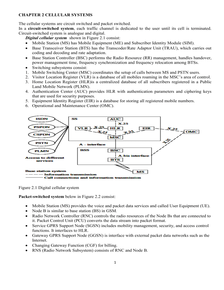
CHAPTER 2 CELLULAR SYSTEMS The cellular systems are circuit switched and packet switched. In a circuit-switched system, each traffic channel is dedicated to the user until its cell is terminated. Circuit-switched system is analogue and digital. Digital cellular system shown in Figure 2.1 consist: Mobile Station (MS) has Mobile Equipment (ME) and Subscriber Identity Module (SIM). Base Transceiver Station (BTS) has the Transcoder/Rate Adaptor Unit (TRAU), which carries out coding and decoding and rate adaptation. Base Station Controller (BSC) performs the Radio Resource (RR) management, handles handover, power management time, frequency synchronization and frequency relocation among BTSs. Switching subsystems consist: 1. Mobile Switching Center (MSC) coordinates the setup of calls between MS and PSTN users. 2. Visitor Location Register (VLR) is a database of all mobiles roaming in the MSC’s area of control. 3. Home Location Register (HLR)is a centralized database of all subscribers registered in a Public Land Mobile Network (PLMN). 4. Authentication Center (AUC) provides HLR with authentication parameters and ciphering keys that are used for security purposes. 5. Equipment Identity Register (EIR) is a database for storing all registered mobile numbers. 6. Operational and Maintenance Center (OMC). Figure 2.1 Digital cellular system Packet-switched system below in Figure 2.2 consist: Mobile Station (MS) provides the voice and packet data services and called User Equipment (UE). Node B is similar to base station (BS) in GSM. Radio Network Controller (RNC) controls the radio resources of the Node Bs that are connected to it. Packet Control Unit (PCU) converts the data stream into packet format. Service GPRS Support Node (SGSN) includes mobility management, security, and access control functions. It interfaces to HLR. Gateway GPRS Support Node (GGSN) is interface with external packet data networks such as the Internet. Changing Gateway Function (CGF) for billing. RNS (Radio Network Subsystem) consists of RNC and Node B. 1 Figure 2.2 Cellular packet system Operation of cellular systems Mobile unit initialization. When a user activates the receiver of the mobile unit, the receiver scans the setup channels. It selects the strongest and locks on for a certain time. Because each site is assigned a different set-up channel, locking onto the strongest set-up channel usually means selecting the nearest cell site. This self-location scheme is used in the idle stage and is user-independent. It has a great advantage because it eliminates the load on the transmission at the cell site for locating the mobile unit. The disadvantage of the self-location scheme is that no location information of idle mobile units appears at each cell site. When the call initiates from the land line to a mobile unit, the paging process is longer. For a large percentage of calls originates at the mobile unit, the use of self-location schemes is justified. After a given period, the self-location procedure is repeated. For land-line originated calls feature “registration” is used. Mobile originated call. The user places the called number into an originating register in the mobile unit and pushes the “send” button. A request for service is sent on a selected set-up channel obtained from a self-location scheme. The cell site receives it, and in directional cell sites (or sectors), selects the best directive antenna for the voice channel to use. At the same time, the cell site sends a request to the mobile telephone switching office (MTSO) via a high-speed data link. The MTSO selects an appropriate voice channel for the call, and the cell site acts on it through the best directive antenna to link the mobile unit. The MTSO also connects the wire-line party through the telephone company zone office. Network originated call. A land-line party dials a mobile number. The telephone company zone office recognizes that the number is mobile and forwards the call to the MTSO. The MTSO sends a paging message to certain cell sites based on the mobile unit number and the search algorithm. Each cell site transmits the page on its own set-up channel. If the mobile is registered, the registered site pages the mobile. The mobile recognizes its own identification on a strong set-up channel, locks onto it, and responds to the cell site. The mobile follows the instruction to tune to an assigned voice channel and initiate user alert. Call termination. When the mobile user turns off the transmitter, a signaling tone transmits to the cell site, and both sides free the voice channel. The mobile resumes monitoring pages through the strongest set-up channel. 2 Handover. During the call, 2 parties are on a traffic channel. When the mobile moves out of the coverage area of a particular cell site, the reception becomes weak. The current cell site requests a handover. The system switches the call to a new frequency channel in a new cell site without either interrupting the call or alerting the user. The call continues while the user is talking. The user does not notice the handover. What is a Cell? The power of radio signals transmitted by the BS decay as the signals travel away from it. A minimum amount of signal strength is needed to be detected by the MS. The region over which the signal strength lies above this threshold value is the coverage area of a BS and it must be a circular region. Such a circle, which gives this actual radio coverage, is called the foot print of a cell. If there is an overlap between any 2 circles or a gap between the 2 adjacent circles then a circular geometry cannot serve as a regular shape to describe cells, therefore regular hexagonal geometry is used as the cells. Figure 2.3 Footprint of cells showing the overlaps and gaps. Frequency reuse [planning] is a technique of reusing frequencies and channels within a communication system to improve capacity and spectral efficiency. Frequency reuse in mobile cellular systems means that frequencies allocated to the service are reused in a regular pattern of cells, each covered by 1 BS. The repeating regular pattern of cells is called cluster. Since each cell is designed to use radio frequencies only within its boundaries, the same frequencies can be reused in other cells not far away without interference, in another cluster. Such cells are called ‘co-channel’ cells. The reuse of frequencies enables a cellular system to handle a huge number of calls with a limited number of channels. Figure 2.4 shows a frequency planning with cluster size of 7, showing the co-channels cells in different clusters by the same letter. The closest distance between the co-channel cells (in different clusters) is determined by the choice of the cluster size and the layout of the cell cluster. Figure 2.4 Frequency reuse technique of a cellular system. 3 The frequency reuse concept can be used in the time domain and the space domain. Frequency reuse in the time domain results in the occupation of the same frequency in different time slots. It is called timedivision multiplexing (TDM). Frequency reuse in the space domain can be divided into two categories. 1. Same frequency assigned in 2 different geographic areas, such as AM or FM radio stations using the same frequency in different cities. 2. Same frequency repeatedly used in a same area in one system. The total frequency spectrum allocation is divided into K frequency reuse patterns. The minimum distance that allows the same frequency to be reused will depend on many factors, such as the number of co-channel cells in the vicinity of the center cell, the type of geographic terrain contour, the antenna height, and the transmitted power at each cell site. The frequency reuse distance D: , where K is the frequency reuse pattern. Figure 2.5 The ratio of distance between cells to the radius of a cell (D/R) If all the cell sites transmit the same power, then K increases and the frequency reuse distance D increases. Increased D reduces the chance that co-channel interference may occur. Theoretically, a large K is desired. However, the total number of allocated channels is fixed. When K is too large, the number of channels assigned to each of K cells becomes small. It is always true that if the total number of channels in K cells is divided as K increases, trunking inefficiency results. The same principle applies to spectrum inefficiency: if the total number of channels are divided into two network systems serving in the same area, spectrum inefficiency increases. Now the challenge is to obtain the smallest number K that can still meet our system performance requirements. This involves estimating co-channel interference and selecting the minimum frequency reuse distance D to reduce co-channel interference. The smallest value of K= 3. When we design a system, the traffic conditions in the area during a busy hour are some of the parameters that will help determine both the sizes of different cells and the number of channels. The maximum number of calls per hour per cell is driven by the traffic conditions at each cell. After the maximum number of frequency channels per cell has been implemented in each cell, then the maximum number of calls per hour can be taken care of in each cell. Reusing an identical frequency channel in different cells is limited by co-channel interference between cells. The cell size is determined by the coverage area of the signal strength in each cell. As long as the cell size is fixed, co-channel interference is independent of the transmitted power of each cell. It means that the received threshold level at the mobile unit is adjusted to the size of the cell. Co-channel interference is a function of a parameter q defined as: q = D/R 4 The parameter q is the co-channel interference reduction factor. When the ratio q increases, co-channel interference decreases. Channel Assignment Strategies 1. Fixed Channel Assignment (FCA) In FCA strategy each cell is allocated a fixed number of voice channels. Any communication within the cell can only be made with the designated unused channels of that particular cell. Suppose if all the channels are occupied, then the call is blocked and subscriber has to wait. This is simplest of the channel assignment strategies as it requires very simple circuitry but provides worst channel utilization. 2. Dynamic Channel Assignment (DCA) In DCA strategy channels are temporarily assigned for use in cells for the duration of the call. Each time a call attempt is made from a cell the corresponding BS requests a channel from MSC. The MSC then allocates a channel to the requesting the BS. After the call is over the channel is returned and kept in a central pool. Handover Process When a user moves from one cell to the other, to keep the communication between the user pair, the user channel has to be shifted from one BS to the other without interrupting the call. When a MS moves into another cell, while the conversation is still in progress, the MSC automatically transfers the call to a new FDD channel without disturbing the conversation. This process is called handover is given in Figure 2.6. Figure 2.6: Handover scenario at two adjacent cell boundary It is not always possible to counter the increasing demand for cellular systems just by increasing the geographical coverage area due to the limitations in obtaining new land with suitable requirements. 2 methods for dealing with an increasing subscriber density: Cell Splitting and Sectoring. The other method, microcell zone concept is treated as enhancing the QoS in a cellular system. Cell-Splitting is based on the cell radius reduction and minimizes the need to modify the existing cell parameters. Cell splitting involves the process of sub-dividing a congested cell into smaller cells, each with its own BS and a corresponding reduction in antenna size and transmitting power. This increases the capacity of a cellular system since it increases the number of times that channels are reused. Since the new cells have smaller radius than the existing cells, inserting these smaller cells, known as microcells, between the already existing cells results in an increase of capacity due to the additional number of channels per unit area. If cells are small, there would have to be more of them and so additional BS will be needed in the system. The challenge in this case is to introduce the new BSs without the need to move the already existing BS towers. The other challenge is to meet the generally increasing demand that may vary quite rapidly between geographical areas of the system. 5 Figure 2.7 Splitting of congested seven-cell clusters. Figure 2.7 shows a cellular layout with seven-cell clusters. Consider that the cells in the center of the diagram are becoming congested, and cell A in the center has reached its maximum capacity. The new smaller cells have half the cell radius of the original cells. At half the radius, the new cells will have onefourth of the area and will consequently need to support one-fourth the number of subscribers. Notice that one of the new smaller cells lies in the center of each of the larger cells. If we assume that BSs are located in the cell centers, this allows the original BSs to be maintained even in the new system layout. However, new base stations will have to be added for new cells that do not lie in the center of the larger cells. The organization of cells into clusters is independent of the cell radius, so that the cluster size can be the same in the small-cell layout as it was in the large-cell layout. Also the signal-to-interference ratio is determined by cluster size and not by cell radius. Consequently, if the cluster size is maintained, the signal-tointerference ratio will be the same after cell splitting as it was before. If the entire system is replaced with new half-radius cells, and the cluster size is maintained, the number of channels per cell will be exactly as it was before, and the number of subscribers per cell will have been reduced. When the cell radius is reduced by a factor, it is also desirable to reduce the transmitted power. The transmit power of the new cells with radius half that of the old cells can be found by examining the received power at the new and old cell boundaries and setting them equal. This is necessary to maintain the same frequency re-use plan in the new cell layout as well. Sectoring is basically a technique which can increase the Signal-to-Interference Ratio (SIR) without necessitating an increase in the cluster size. The co-channel interference in a cellular system may be decreased by replacing a single omni-directional antenna at the base station by several directional antennas, each radiating within a specified sector. In Figure 2.8 a cell is shown which has been split into three 120o sectors. The base station feeds three 120o directional antennas, each of which radiates into one of the three sectors. Figure 2.8: A cell divided into three 120o sectors The channel set serving this cell has also been divided, so that each sector is assigned one-third of the available number cell of channels. This technique for reducing co-channel interference where by using suitable directional antennas, a given cell would receive interference and transmit with a fraction of available co-channel cells is called 'sectoring'. In a seven-cell-cluster layout with 120o sectored cells, it can be easily understood that the mobile units in a particular sector of the center cell will receive co-channel interference from only 2 of the first-tier cochannel base stations, rather than from all six. BS in the center cell will receive co-channel interference from mobile units in only 2 of the co-channel cells. Some cellular systems divide the cells into 60o sectors. 6 Microcell Zone Concept The increased number of handovers required when sectoring is employed, which results in an increased load on the switching and control link elements of the mobile system. To overcome this problem, a new microcell zone concept has been proposed. As shown in Figure 2.9, this scheme has a cell divided into 3 microcell zones, with each of the three zone sites connected to the base station and sharing the same radio equipment. Figure 2.9: The micro-cell zone concept Benefits of the micro-cell zone concept: Interference is reduced. Handoffs are reduced since the microcells within the cell operate at the same frequency; no handover occurs when the mobile unit moves between the microcells. The zone site equipment being small can be mounted on the side of a building or on poles. System capacity is increased. The new microcell knows where to locate the mobile in a particular zone of the cell and deliver the power to that zone. Since the signal power is reduced, the microcells can be closer and result in an increased system capacity. 7
