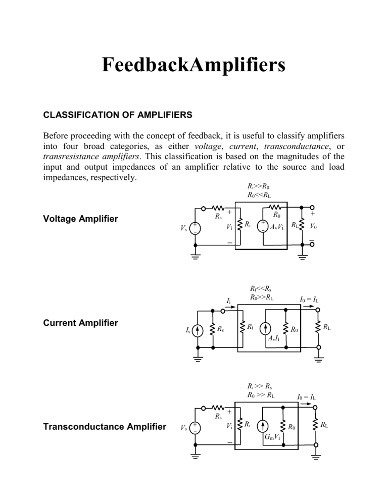
FeedbackAmplifiers CLASSIFICATION OF AMPLIFIERS Before proceeding with the concept of feedback, it is useful to classify amplifiers into four broad categories, as either voltage, current, transconductance, or transresistance amplifiers. This classification is based on the magnitudes of the input and output impedances of an amplifier relative to the source and load impedances, respectively. Ri>>R0 R0<<RL Voltage Amplifier Rs Vs + + Vi + R0 Ri + AvVi RL Ii Current Amplifier Is Ri<<Rs R0>>RL Ri Rs V0 I0 = IL R0 RL AvIi Ri >> Rs R0 >> RL Rs Transconductance Amplifier Vs + I0 = IL + Vi Ri R0 GmVi RL Ii Ri << Rs R0 << RL + R0 Rs Is Transresistance Amplifier + Ri RmIi RL V0 The characteristics of the four ideal amplifiers are summarized in Table 9.1. Table 9.1 Ideal amplifier characteristics __________________________________________________________________ Amplifier type ___________________________________________________________ Parameter Voltage Current Transconductance Transresistance __________________________________________________________________ Ri ……………………… 0 0 R0 ……………………… 0 0 Transfer characreristic ... V0 = AvVs IL = AiIs IL = GmVs V0 = RmIs Reference ……………... Fig. 7.1 Fig. 7.2 Fig. 7.3 Fig. 7.4 _______________________________________________________________________________ THE FEEDBACK CONCEPT Ii Signal source Comparator or mixer network Basic amplifier Forward transfer gain A + Vi If Vf Feedback network Reverse transfer gain + Feedback amplifier I0 = IL I + V + Sampling network + V0 RL Sampling Network Voltage sampler I0 Current sampler I0 Basic amplifier A RL Basic amplifier A + V0 Feedback network Feedback network (a) RL (b) Feedback connections of the output of a basic amplifier, sampling the output (a) voltage and (b) current. Comparator, or Mixer Network Source Series mixer + Rs + Shunt mixer Source Vi Vs Ii Rs A A Is If Vf + (a) (b) Feedback connections at the input of a basic amplifier: (a) Series comparison and (b) Shunt mixing. Amplifier Topologies + + Vs Vi V0+ Voltage amplifier RL I0 = IL + V0 + + Vs Transconductance amplifier Vi + Vf + I0=Vf RL (i) (ii) Ii + Is Ii I0 = IL Vi + Current amplifier Is Vi I0=If RL (iii) V0=If + Transresistance amplifier RL V0 (iv) Feedback amplifier topologies. The source resistance is considered to be part of the amplifier: (i) Voltage amplifier with voltage─series feedback, (ii) Transconductance amplifier with current─series feedback, (iii) Current amplifier with current─shunt feedback, and (iv) Transresistance amplifier with voltage─shunt feedback. THE TRANSFER GAIN WITH FEEDBACK Comparator or mixer Xs Input signal Differnce signal Xd = Xs - Xf = Xi + Xf = X0 Feedback signal Basic amplifier A Output signal X0 = AXi Feedback network RL External load Schematic representation of a single─loop feedback amplifier. Xd Xs Xf Xi (9.1) Since Xd represents the difference between the applied signal and that fed back to the input, Xd is called the difference, error, or comparison, signal. The reverse transmission factor is defined by X (9.2) f X0 The factor is often a positive or a negative real number, but in general, is a complex function of the signal frequency. The symbol X0 is the output voltage,or the output (load) current. The transfer gain A is defined by X (9.3) A 0 Xi By substituting Equations (9.1) and (9.2) into Equation (9.3), we obtain for Af the gain with feedback, X A (9.4) Af 0 X s 1 A The quantity A in Equations (9.3) and (9.4) represents the transfer gain of the corresponding amplifier without feedback, but including the loading of the network, RL and Rs. In the following section many of the desirable features of feedback are deduced, starting with the fundamental relationship given in Equation (9.4). If Af < A , the feedback is termed negative, or degenerative. If Af > A , the feedback is termed positive, or regenerative. From Equation (9.4) we see that, in case of negative feedback, the gain of the basic ideal amplifier with feedback is divided by the factor 1 A , which exceeds unity. Loop Gain The signal Xd in Figure 9.8 is multiplied by A in passing through the amplifier, is multiplied by in transmission through the feedback network, and is multiplied by 1 in the mixing or differencing network. Such a path takes us from the input terminals around the loop consisting of the amplifier and feedback network back to the input; the product A is called the loop gain, or return ratio. The difference between unity and the loop gain is called the return difference D 1 A. Also, the amount of feedback introduced into an amplifier is often expressed in decibels by the definition A 1 N dB of feedback 20 log f 20 log (9.5) A 1 A If negative feedback is under consideration, N will be a negative number. GENERAL CHARACTERISTICS OF NEGATIVE FEEDBACK AMPLIFIERS Af < A Since negative feedback reduces the transfer gain, why is it used? The answer is that many desirable characteristics are obtained for the price of gain reduction. We now examine some of the advantages of negative feedback. Desensitivity of Transfer Amplification dAf 1 dA Af 1 A A (9.6) Hence the sensitivity is 1 1 A . If for example, the sensitivity is 0.1, the percentage change in gain with feedback is one-tenth the percentage variation in amplification if no feedback is present. The reciprocal of the sensitivity is called the desensitivity D, or D 1 A (9.7) A D In particular, if A 1, then Af (9.8) A A 1 (9.9) 1 A A and the gain may be made to depend entirely on the feedback network. The worst offenders with respect to stability are usually the active devices (transistors) involved. If the feedback network contains only stable passive elements, the improvements in stability may indeed be pronounced. Af Advantages of Negative Feedback (a) Frequency Distortion (b) Nonlinear Distortion (c) Reduction of Noise
