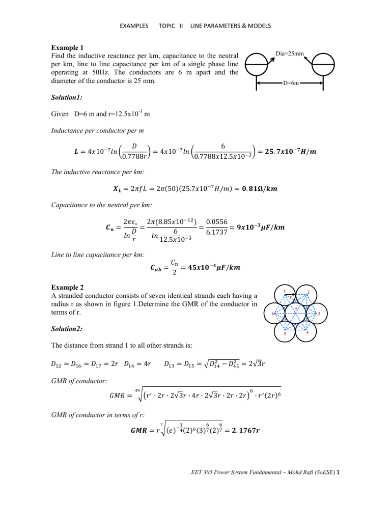
EXAMPLES TOPIC II LINE PARAMETERS & MODELS Example 1 Find the inductive reactance per km, capacitance to the neutral per km, line to line capacitance per km of a single phase line operating at 50Hz. The conductors are 6 m apart and the diameter of the conductor is 25 mm. Dia=25mm D=6m Solution1: Given D=6 m and r=12.5x10⁻³ m Inductance per conductor per m 4 10 6 0.7788 12.5 10 4 10 0.7788 . / The inductive reactance per km: 2 2 50 25.7 10 / . / Capacitance to the neutral per km: 2 2 8.85 10 6 12.5 10 0.0556 6.1737 / Line to line capacitance per km: / 2 Example 2 A stranded conductor consists of seven identical strands each having a radius r as shown in figure 1.Determine the GMR of the conductor in terms of r. 1 2 r 7 6 Solution2: 5 3 4 The distance from strand 1 to all other strands is: 2 4 2√3 GMR of conductor: · 2 · 2√3 · 4 · 2√3 · 2 · 2 · 2 GMR of conductor in terms of r: 2 3 2 . EET 305 Power System Fundamental ~ Mohd Rafi (SoESE) 1 EXAMPLES TOPIC II LINE PARAMETERS & MODELS Example 3 One circuit of a single phase transmission line composed of three solid wires, each 5mm in diameter. The return circuit composed of two wires, each 10mm in diameter. The arrangement of the conductor is shown in figure 3. Find the inductance due to current in each side of the line and the inductance of the complete line. 10m a a’ b b’ 5m 5m c Solution 3: 10 10 10 √10 14.14 5 11.18 Geometric Mean Distance (GMD): 10 11.18 11.18 10 14.14 11.18 . Geometric Mean Radius (GMR): For three solid wires (x): 5 10 0.7788 2.5 10 62500 5 5 5 10 . For two solid wires (y): 5 5 0.7788 5 10 5 5 . The inductance of conductor x is, 2 10 2 10 11.2 0.4259 . / 2 10 11.2 0.1395 . / The inductance of conductor y is, 2 10 The total inductance will be, 6.54 10 8.77 10 / . / EET 305 Power System Fundamental ~ Mohd Rafi (SoESE) 2 EXAMPLES TOPIC II LINE PARAMETERS & MODELS Example 4 A three phase transmission line has its conductors at the corner of an equilateral triangle with side 4.5 m. The diameter of each conductor is 20 mm. Find the inductance per km and capacitance to the neutral per km of the line. D D D Solution 4: D=4.5 m and r =10x10-3 m r’=0.7788x10x10-3 =7.788x10⁻³ m For three phase transmission line, 2 10 2 10 4.5 7.788 10 Inductance per km: . / 8.85 10 4.5 10 10 0.0556 6.10924 Capacitance to neutral per km: 2 2 . / Example 5 Find the inductive reactance per km at 50 Hz of three phase bundled conductor line with two conductors per phase as shown in figure 5. Diameter of each conductor is 30 mm. 0.4m a 0.4m a’ b 0.4m b’ 9m c c’ 9m Solution 5: GMR, for the two sub-conductor bundle: 0.7788 15 10 0.4 . Distance from conductor to another, Dab=Dbc=9m, Dab’=Dbc’=9.4m, Da’b=Db’c=8.6m, Da’b’=Db’c’=9m, Dac=18m, Dac’=18.4m, Da’c=17.6m, Da’c’=18m EET 305 Power System Fundamental ~ Mohd Rafi (SoESE) 3 EXAMPLES TOPIC II LINE PARAMETERS & MODELS GMD between each phase group: 9 9.4 8.6 9 8.9956 9 9.4 8.6 9 8.9956 17.9978 18 18.4 17.6 18 The equivalent GMD, 8.9956 8.9956 17.9978 Inductance is given by 2 10 11.3351 0.068 2 10 . . / Inductance reactance per km is given by 2 2 . 50 10.23 10 / Example 6 A 132kV 3 phase single circuit bundle conductor line with two sub-conductors per phase is shown in figure 6. The radius of each conductor is 10mm. The centre to centre distance between adjacent phases is 12m and the spacing between the sub-conductors is 0.5m. Find the capacitance per km. Solution 6: Distance between a bundles of conductors to another bundle: 12 , 12 , 24 Geometric Mean Distance (GMD): 12 12 24 15.119 GMR, rb for two sub-conductor bundle: √ 10 10 0.5 0.0707 Line capacitance to neutral per km: 0.0556 0.0556 15.119 0.0707 . / EET 305 Power System Fundamental ~ Mohd Rafi (SoESE) 4 EXAMPLES TOPIC II LINE PARAMETERS & MODELS Example 7 A 345 kV double circuit three phase transposed line is composed of two ACSR 1431000-cmil, 45/7 Bobolink conductor per phase with vertical conductor configuration as shown in figure 7. The conductors have a diameter of 1.427 in and a GMR of 0.564 in. The bundle spacing in 18 in. Find the inductance and capacitance per phase per km of the line. a S11=11m c’ H12=7m b b’ S22=16.5m H23=6.5m S33=12.5m c a’ Solution 7: Given that, GMR=0.564 inch= 0.01433 m Conductor diameter=1.427 inch=0.03625 m Bundle spacing=18 inch=0.4572 m Distance of conductors: Dab’=15.43m, Dbc’=15.43m, Dca’=12.50m, Dab=7.52m, Dbc=6.80m, Dca=13.52m, Daa’=17.90m, Da’b=15.21m, Db’c=15.21m, Dc’a=11.00m, Dbb’=16.50m, Da’b’=6.80 m Db’c’=7.52m Dc’a’=13.52m Dcc’=17.90m GMD between each phase group: 15.43 7.52 15.21 6.80 10.4666 15.43 6.80 15.21 7.52 10.4666 12.5 13.52 11.00 13.52 12.5911 The equivalent Geometric Mean Distance (GMD): 10.4666 10.4666 12.5911 11.132 Then, GMR for each subconductor and spacing d: 0.01432 0.4572 0.03625 2 √ 0.4572 0.08091 0.091 GMR of each phase group for inductance, 0.08091 17.9 0.08091 16.5 0.08091 17.9 1.2034 1.1554 1.2034 EET 305 Power System Fundamental ~ Mohd Rafi (SoESE) 5 EXAMPLES TOPIC II LINE PARAMETERS & MODELS GMR of each phase group for capacitance, 0.091 17.9 0.091 16.5 0.091 17.9 1.276 1.225 1.276 The equivalent GMR, 1.2034 1.1554 1.2034 1.276 1.225 1.276 Inductance per phase: 0.2 0.2 Capacitance per phase: 0.0556 11.132 1.187 0.0556 11.132 1.2587 1.187 1.2587 . / . / Example 8 A 220 kV, 150 MVA, 60 Hz, three phase transmission line, 140 km long, characteristic parameters of the transmission line are, r = 0.12 Ω/km x = 0.88 Ω/km y = 4.1 x 10 -6 S/km The voltage at the receiving end of the transmission line is 210 kV. If considered transmission line is a short length. Find, a) What is series impedance and shunt admittance of this transmission line? b) What is the sending end voltage if the line is supplying rated voltage and apparent power at 0.85 pf lagging? At unity pf? At 0.85 leading pf? c) What is the voltage regulation of the transmission line for each of the cases (b)? d) What is the efficiency of the transmission line when it is supplying rated apparent power at 0.85 pf lagging? Solution 8: a) The series resistance, and series reactance of this transmission line are : R = r.d = (0.12 Ω/km) (140 km) = 16.8 Ω XL = x.d = (0.88 Ω/km) (140 km) = 123.2 Ω b) The current out of this transmission line will be given by S √3 √3VLLR IR 150 √3 210 412 EET 305 Power System Fundamental ~ Mohd Rafi (SoESE) 6 EXAMPLES TOPIC II LINE PARAMETERS & MODELS The line to neutral voltage out of the line will be, 210 √3 121 Since this transmission line as short. The line to neutral voltage VS at the sending end of the line when the power factor is 0.85 lagging will be, 121 0° 412 31.8° 16.18 √3 158 123.3 158 14.4° The line to neutral voltage VS at the sending end of the line when the power factor is 1.0 will be, 121 0° 412 0° 16.18 √3 137.4 123.3 137.4 21.6° The line to neutral voltage VS at the sending end of the line when the power factor is 0.85 leading will be, 121 0° 412 31.8° 16.18 VLLS √3 110.3k V 123.3 110.3 25.0° c) The voltage regulation of a transmission line is given by 100% The no load received voltage will be the same as the source voltage, since there will be no current flowing in the line at no load conditions. The full load received voltage will be 210 kV. The resulting voltage regulation at 0.85 power factor lagging is . 274 210 100% 210 . % The resulting voltage regulation at unity power factor is 238 210 100% 210 . % The resulting voltage regulation at 0.85 power factor leading is . 191 210 100% 210 . % EET 305 Power System Fundamental ~ Mohd Rafi (SoESE) 7 EXAMPLES TOPIC II LINE PARAMETERS & MODELS d) The output power from the transmission line at a power factor of 0.85 lagging is Pout = 3 VR IR Cos θR = 3 (121kV) (412A) (0.85) = 127 kW The input power from the transmission line is Pin = 3 VS IS cos θS= 3(158kV) (412A) Cos [14.1-(-31.8)] = 135.7 kW The resulting transmission line efficiency at full load and 0.85 power factor lagging is 127 135.7 100% 100% . % Example 9 A three phase 132 kV transmission line is connected to a 50 MW load a 0.85 power factor lagging. The line constants (resistance and susceptance) of the 85 km long line are Z=95∠78° Ω Y=1x10⁻³∠90° mho Using nominal T circuit representation calculate a) The ABCD of the line b) Sending end voltage c) Sending end current d) Sending end power factor e) Efficiency of transmission Solution 9: a) The ABCD of the line The receiving end voltage is 132 76.21 √3 The receiving end current is 50 10 √3 132 10 0.85 257.29 For T circuit representation (Medium Line) 1 1 4 1 2 1 1 10 90° 95 78° . 2 1 1 10 95 78° 90° 95 78° 4 C=Y=0.001∠90° D=A=0.9536∠0.6° 1 . ° . . ° EET 305 Power System Fundamental ~ Mohd Rafi (SoESE) 8 EXAMPLES TOPIC II LINE PARAMETERS & MODELS b) Sending end voltage VS=AVR+BIR VS= (0.9536∠0.6°) (76.21∠0°kV) + (92.79∠78.3°) (257.29∠-31.79°) =90.92∠11.5°kV Sending end line to line voltage, VLLS=90.92x√3=15.46kV c) Sending end current is IS=CVR+DIR IS=0.001∠90(76.21∠0°kV) + (0.9536∠0.6°) (257.29∠-31.79°) = 215.18∠-14.27° d) Sending end power factor PF = Cosθ = Cos (11.5°+14.27°) =0.9 e) Efficiency of transmission line √3 √3 100% √3 132 257.29 0.85 √3 157.46 215.18 0.9 . % Example 10 Find the voltage at the generator end of the following three phase line: Length of the line, km 320 Resistance, ohm/km 0.055 Reactance, ohm/km 0.505 Susceptance, mho/km 3.24x10⁻⁶ Load measured at the load end of the line is 60 MW at 0.80 power factor lagging at 132 kV, using long line equation. a) Find the ABCD of the line b) Find the sending end voltage, current and power factor Solution 10: a) The ABCD constants, Given, z = r +jx = 0.055 + j0.505 = 0.508 ∠83.78° y = j3.24x10-6 = 3.24x10⁻⁶∠90° Also, the propagation constant; 3.24 10 90° 0.508 83.78° 1.283 10 86.89° γl = (1.283x10⁻³) (320km) = 0.411∠86.89 = 0.022+ j0.4104 EET 305 Power System Fundamental ~ Mohd Rafi (SoESE) 9 EXAMPLES TOPIC II LINE PARAMETERS & MODELS Therefore, Attenuation constant (α) and phase constant (β): αl =0.022 and βl=0.4104 Cosh γl=cosh (αl + jβl) = (coshαl cosβl) + j (sinhαl sinβl) =cosh (0.022) cos (0.4104) +j (sinh (0.022) sin (0.4104)) =0.917∠0.55° Sinh γl=sinh (αl + jβl) = (sinhαl cosβl) + j (coshαl sinβl) = (sinh (0.022) cos (0.4104)) + j (cosh (0.022) sin (0.4104)) =0.3995∠87.13° Characteristic impedance: 0.508 83.8° 90° 3.24 10 Now we have, . . ° A=cosh γl=0.917∠0.55° B=ZC sinh γl = (395.7∠-3.11°) (0.3995∠87.13°) =158.19∠84.02° 1 0.3995 87.13° 395.97 3.11° sinh . . ° D=A b) Sending end voltage, current and PF 132 √3 And 60 √3 132 0.8 76210 0° 36.86° 328.04 36.86° VS=AVR+BIR=112067.92∠20.21° V =112.06792∠20.21°kV Sending end line voltage: √3 112.06972 . Also, Sending end line current: IS=CVR+DIR=262.90∠-22.61°A Sending end power factor PF: PF=cos θ=cos (20.21°+22.61°) =0.73 lagging EET 305 Power System Fundamental ~ Mohd Rafi (SoESE) 10

