International Journal of Trend in Scientific Research and Development (IJTSRD)
Volume 3 Issue 5, August 2019 Available Online: www.ijtsrd.com e-ISSN: 2456 – 6470
Deaf Sign Language using Automatic Hand Gesture
Robot Based on Microcontroller System
Hay Man Oo1, Khin Thandar Tun1, May Lwin Thant2
1Lecturer, 2Assistant
1,2Department
Lecturer
of Electronic Engineering, Technological University, Meiktila, Myanmar
How to cite this paper: Hay Man Oo |
Khin Thandar Tun | May Lwin Thant "Deaf
Sign Language using Automatic Hand
Gesture
Robot
Based
on
Microcontroller
System" Published
in
International
Journal of Trend in
Scientific Research
and Development
IJTSRD27876
(ijtsrd), ISSN: 24566470, Volume-3 | Issue-5, August 2019,
pp.2132-2136,
https://doi.org/10.31142/ijtsrd27876
Copyright © 2019 by author(s) and
International Journal of Trend in Scientific
Research
and
Development Journal.
This is an Open
Access article distributed under the terms
of the Creative Commons Attribution
License
(CC
BY
4.0)
(http://creativecommons.org/licenses/by
/4.0)
ABSTRACT
Nowadays, the gesture is one of the most natural interaction methods of the
human being. In fact, a great percentage of the human communication is based
on visual communication rather than verbal communication. The robot and the
gesture device are connected wirelessly via Bluetooth modules. The wireless
communication enables the user to interact with the robot in a more friendly
way. Gesture controlled robot is a robot which has been controlled by simple
gestures. The user needs to wear a gesture device which includes a sensor. The
sensor records the movement of hand in a specific direction which results in
the movement of the robot in the respective direction. This robot helps people
with deafness and dumbness by showing hand gestures assigned English
alphabets. This paper discusses the design and implementation of deaf sign
language using automatic hand gesture robot using Bluetooth and Arduino
board.
KEYWORDS: Arduino UNO, Arduino NANO, HC-05 Bluetooth module, WTV-020 SD
sound module, I2C module, Flex sensor, MG90S servo motor, servo driver, LCD, DC
convector, Speaker
I.
INTRODUCTION
The communication between deafness and hearing person poses to be an
important disadvantage compared to communication between blind and
ancient visual people. Sign language is a way by which the gestures made by the
user are used for communication.
The blind people speaks freely by implies that of ancient
language whereas the dumb has own manual visual language
referred to as language. A dumb communication interpreter
is also a tool that interprets the hand gestures to sensibility
speech. In this system, the gestures are converted into text
message for communication. Basically there are two main
parts of this paper that are transmitter and receiver. Flex
sensors mainly attached on the glove. Main goals of the
system are to convert hand gestures to auditory speech for
communication between deaf and normal people and to
convert speech to readable text for communication between
deaf and normal people.
II.
System Block Diagram
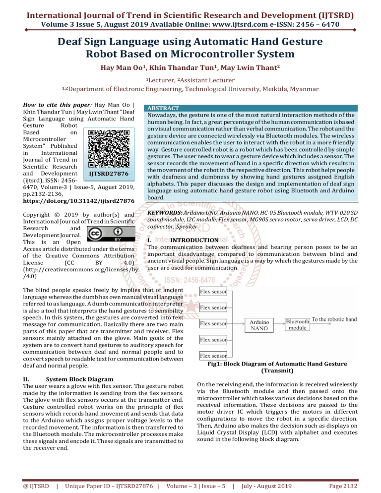
The user wears a glove with flex sensor. The gesture robot
made by the information is sending from the flex sensors.
The glove with flex sensors occurs at the transmitter end.
Gesture controlled robot works on the principle of flex
sensors which records hand movement and sends that data
to the Arduino which assigns proper voltage levels to the
recorded movement. The information is then transferred to
the Bluetooth module. The microcontroller processes make
these signals and encode it. These signals are transmitted to
the receiver end.
@ IJTSRD
|
Unique Paper ID – IJTSRD27876 |
Fig1: Block Diagram of Automatic Hand Gesture
(Transmit)
On the receiving end, the information is received wirelessly
via the Bluetooth module and then passed onto the
microcontroller which takes various decisions based on the
received information. These decisions are passed to the
motor driver IC which triggers the motors in different
configurations to move the robot in a specific direction.
Then, Arduino also makes the decision such as displays on
Liquid Crystal Display (LCD) with alphabet and executes
sound in the following block diagram.
Volume – 3 | Issue – 5
|
July - August 2019
Page 2132
International Journal of Trend in Scientific Research and Development (IJTSRD) @ www.ijtsrd.com eISSN: 2456-6470
showed servo angle as integer. The servo is driven by using
PWM driver library "setPWM (servo pin,address,pwmvalue).
Software Implementation to Find Header Ring Finger (R)
Character
c=bluetooth.find('R');
if(c=true)
{
R = bluetooth.parseInt();
Serial.print(R);
Serial.print(" ");
// pwm.setPWM(3, 0, pulseWidth(R));
}
Fig 2: Block Diagram of Robotic Hand Gesture
(Receive)
III.
Implementation
A. Software Implementation
Software Implementation to Find Header Thumb Finger
(T) Character
c=bluetooth.find('T');
if(c=true)
{
T = bluetooth.parseInt();
Serial.print(T);
Serial.print(" ");
// pwm.setPWM(5, 0, pulseWidth(T));
}
It is to find header thumb finger (T) character. If T was not
found, result c is false and if it was found, result c is true. The
header T and servo angle integer are separated and showed
servo angle as integer. The servo is driven by using PWM
driver library "setPWM (servo pin,address,pwmvalue).
Software Implementation to Find Header Index Finger
(I) Character
c=bluetooth.find('I');
if(c=true)
{
I = bluetooth.parseInt();
Serial.print(I);
Serial.print(" ");
// pwm.setPWM(1, 0, pulseWidth(I))
}
This is to find header index finger (I) character. If I was not
found, result c is false and if it was found, result c is true. The
header I and servo angle integer are separated and showed
servo angle as integer. The servo is driven by using PWM
driver library "setPWM (servo pin,address,pwmvalue).
Software Implementation to Find Header Middle Finger
(M)) Character
c=bluetooth.find('M');
if(c=true)
{
M = bluetooth.parseInt();
Serial.print(M);
Serial.print(" ");
// pwm.setPWM(2, 0, pulselength(M));
This is to find header middle finger (M) character. If M was
not found, result c is false and if it was found, result c is true.
The header M and servo angle integer are separated and
@ IJTSRD
|
Unique Paper ID – IJTSRD27876 |
This is to find header ring finger (R) character. If R was not
found, result c is false and if it was found, result c is true. The
header R and servo angle integer are separated and showed
servo angle as integer. The servo is driven by using PWM
driver library "setPWM (servo pin,address,pwmvalue).
Software Implementation to Find Header Pinkie
Finger(P) Character
c=bluetooth.find('P');
if(c=true)
{
P = bluetooth.parseInt();
Serial.print(P);
Serial.print(" ");
// pwm.setPWM(4, 0, pulseWidth(P));
}
This is to find header pinkie finger (P) character. If P was not
found, result c is false and if it was found, result c is true. The
header P and servo angle integer are separated and showed
servo angle as integer. The servo is driven by using PWM
driver library "setPWM (servo pin,address,pwmvalue).
Software Implementation for Alphabet B
B alphabet is displayed on LCD and turned on voice sound.
Delay time is one second to stop voice sound and be clear
displayed alphabet on LCD.
if(T<50 && I>75 &&M>75 && R>75 && P>75)
{
lcd.print("B");
Serial.println ("B");
wtv020sd16p.asyncPlayVoice(1);
delay(1000);
wtv020sd16p.stopVoice();
lcd.clear();
}
Software Implementation for Alphabet D
D alphabet is displayed on LCD and turned on voice sound.
Delay time is one second to stop voice sound and be clear
displayed alphabet on LCD.
if(T<20 && I>65 &&M<20 && R<20 && P<20)
{
lcd.print("D");
Serial.println ("D");
wtv020sd16p.asyncPlayVoice(3);
wtv020sd16p.stopVoice();
delay(1000);
lcd.clear();
}
Volume – 3 | Issue – 5
|
July - August 2019
Page 2133
International Journal of Trend in Scientific Research and Development (IJTSRD) @ www.ijtsrd.com eISSN: 2456-6470
Software Implementation
plementation for Alphabet F
F alphabet is displayed on LCD and turned on voice sound.
Delay time is one second to stop voice sound and be clear
displayed alphabet on LCD.
if(T>20&&T<80 && I>=0&&I<50 &&M>60 && R>60 &&
P>60)
{
lcd.print("F");
Serial.println ("F");
wtv020sd16p.asyncPlayVoice(5);
wtv020sd16p.stopVoice();
delay(1000);
lcd.clear();
}
Software Implementation for Alphabet G
G alphabet is displayed on LCD and turned on voice sound.
Delay time is one second to stop voice sound and be clear
displayed alphabet on LCD.
thumb, index, middle, ring and pinkie. Then the servo angle
passes the 16 channels PWM servo driver
driv and the servo
driver rotates the servo motor by applying the pulse width
modulation. Therefore, the servo driver supported to the
current of servo motor which loaded current base on
required operated torque. Then, Arduino UNO executes the
sign language converted into English alphabets display on
LCD. Finally, Arduino UNO commands the sound module.
The sounds of alphabet are stored in 2 GB SD card that
installed on sound module and Arduino commands the
sound module to talk the speaker what received. The sound
s
module of CLK pin is plugged in Arduino UNO of digital pin 3,
the sound module of data pin is plugged in Arduino UNO of
digital pin 4, the sound module of busy pin is plugged in
Arduino UNO of digital pin 5 and reset pin is plugged in
Arduino UNO of digital
igital pin 9. Main goals of the system are
that converting hand gestures into auditory speech for
communication to be readable text for communication
between deaf and normal people.
if(T>75 && I>65 &&M<20 && R<20 && P<20)
{
lcd.print("G");
Serial.println ("G");
wtv020sd16p.asyncPlayVoice(6);
wtv020sd16p.stopVoice();
delay(1000);
lcd.clear();
Software Implementation for Alphabet K
K alphabet is displayed
splayed on LCD and turned on voice sound.
Delay time is one second to stop voice sound and be clear
displayed alphabet on LCD.
Fig 3: Circuit Diagram of Automatic Hand Gesture
(Transmit)
if(T<75 && I>65 &&M>65 && R<20 && P<20)
{
lcd.print("K");
Serial.println ("K");
wtv020sd16p.asyncPlayVoice(10);
wtv020sd16p.stopVoice();
delay(1000);
lcd.clear();
B. Hardware Implementation
The design is used flex sensors to sense the motion of
fingers. It is five sensors that were arranged in a hand glove
which makes the sensors comfortable to wear. The glove is
mounted
unted with flex sensors that change their resistance value
when bending. They are attached to one side of voltage
divider with resistor of a constant value on the other side.
The Arduino reads the voltage change when the sensors are
bent and triggers the servos
ervos to move a proportional amount.
The side of robotic hand is used 12 V external power supply.
The analog values obtained from the flexible sensor are
transmitted to the robotic hand gesture side via Bluetooth
module. These values which are converted in
into digital
operation and then sent to the Arduino UNO platform
connected to the robotic hand via the Bluetooth module. The
Bluetooth modules are connected at the control glove
(human hand) and given the signal to the Arduino of robotic
hand. The Arduino UNO
O receives the signals and executes the
signals with three main functions. In the first step, Arduino
UNO finds the header and separates the servo angle for
@ IJTSRD
|
Unique Paper ID – IJTSRD27876
27876 |
Fig 4: Circuit Diagram of Robotic Hand Gesture
(Receive)
IV.
Results
Firstly, the flex sensors are powered from 9 V battery. The
side of the robotic hand supplies 12 V to the Arduino and
another supply to the step down power module. After the
flex sensors are power ON, the robotic hand was initializing
on the normal position. Fig 5 shows robotic hand gesture
under the power OFF state. The condition of robotic hand is
not ready for showing hand gesture in normal position. Fig 6
shows robotic hand gesture under the power
pow ON state. The
robotic hand is ready for showing hand gesture when the
flex sensor is bending.
Volume – 3 | Issue – 5
|
July - August 2019
Page 2134
International Journal of Trend in Scientific Research and Development (IJTSRD) @ www.ijtsrd.com eISSN: 2456-6470
Testing for Alphabet F
This testing is alphabet F for the robotic hand and LCD.
Fig 5: Robotic Hand Gesture under the Power OFF
State
Fig 6: Robotic Hand Gesture under the Power ON State
Testing for Alphabet B
This testing is alphabet B for the robotic hand and LCD.
Fig 9: Testing Alphabet F
Testing for Alphabet G
This testing is alphabet F for the robotic hand and LCD.
Fig7: Testing Alphabet B
Testing for Alphabet D
This testing is alphabet D for the robotic hand and LCD.
Fig 10: Testing Alphabet G
Testing for Alphabet K
This testing is alphabet K for the robotic hand and LCD.
Fig 8: Testing Alphabet D
@ IJTSRD
|
Unique Paper ID – IJTSRD27876
27876 |
Volume – 3 | Issue – 5
|
July - August 2019
Page 2135
International Journal of Trend in Scientific Research and Development (IJTSRD) @ www.ijtsrd.com eISSN: 2456-6470
VI.
REFERENCES
[1] Omer, K. and Mustafa, C. K.: Robot Hand Making
Copying Finger Motion, (2016).
[2] Saurabh A.: Implementation of Wireless Gesture
Controlled Robotic Arm,, (2015).
[3] Das, A. K: Design and Realization of Prosthetic Hand,
Hand
(2013).
[4] Michael,l, M. and Nicholas, W.: Arduino Cookbook,
(2011).
Fig11: Testing Alphabet K
V.
Conclusion
Sign language helps to bridge the gap between those who
can hear and those who cannot. All those people are not
understanding about this language. People use Bluetooth
device for the communication whose range is descent for 30
m. Hence, this device works wirelessly used for around 30 m.
The design and construction of this device were properly
manufactured at a very low price with high usability. This is
a very noble approach to communicate bidirectional
between normal and disable
able person. This is very useful for
the disable person as with the help of this device. The results
of the flex sensor have also been displayed at the robotic
hand wirelessly using Bluetooth in future Wifi technology
that has been used to increase the range
ge of the device.
@ IJTSRD
|
Unique Paper ID – IJTSRD27876
27876 |
[5] Ramaiah, P. S.: Microcontroller Based Four Fingered
Robotic Hand, (2011).
[6] Matthias, R.: Wave like Egyptian Accelerometer Based
Gesture Recognition for Culture Specific Interactions,
(2007).
[7] Olawale, J.: Development
elopment of Microcontroller Based
Robotic Arm, (2007).
[8] Carrozza, M. C.: The Development of Novel Prosthetic
Hand-Ongoing
Ongoing Research and Preliminary Results,
(2002).
[9] Ambrose, R. O.: Biomimetic Compliance Control of Robot
Hand by Considering Structures of Human Finger,
Finger
(2000).
Volume – 3 | Issue – 5
|
July - August 2019
Page 2136


