International Journal of Trend in Scientific Research and Development (IJTSRD)
Volume 3 Issue 5, August 2019 Available Online: www.ijtsrd.com e-ISSN: 2456 – 6470
Simulation and Results of Static Var Compensator for Electric
Arc Furnace (No 1 Iron and Steel Mill, Pyin Oo Lwin, Myanmar)
Dr. Thet Mon Aye
Lecturer, Department of Electrical Power Engineering, West Yangon Technological University, Yangon, Myanmar
How to cite this paper: Dr. Thet Mon Aye
"Simulation and Results of Static Var
Compensator for Electric Arc Furnace (No
1 Iron and Steel Mill, Pyin Oo Lwin,
Myanmar)"
Published
in
International
Journal of Trend in
Scientific Research
and Development
(ijtsrd), ISSN: 2456IJTSRD26613
6470, Volume-3 |
Issue-5, August 2019, pp.1192-1197,
https://doi.org/10.31142/ijtsrd26613
Copyright © 2019 by author(s) and
International Journal of Trend in Scientific
Research and Development Journal. This
is an Open Access article distributed
under the terms of
the
Creative
Commons Attribution
License
(CC
BY
4.0)
(http://creativecommons.org/licenses/by
/4.0)
ABSTRACT
Electric arc furnace is unbalanced, nonlinear and time varying loads, which can
cause many problems in the power system. Voltage variation problem is the
major focus of the power system because the loads can vary anytime. Power
quality issue has a very high attractive for power system engineers and try to
solve these problems by several effective ways. In this thesis, Static Var
Compensator (SVC), thyristor controlled reactor compensation with thyristor
switched capacitor (TCR-TSC) type is designed and its performance is
simulated in the case studies. This unique design of this device (SVC) is used
for reactive power compensation for nonlinear loads such as electric arc
furnace (EAF) in an industrial plant. Moreover, the SVC is more effectively
enhance the voltage stability. Single tuned passive harmonic filter can reduce
total harmonic distortion (THD) caused by thyristor controlled reactor of SVC.
The installation site for this thesis is No. 1 Iron and Steel Mill, Pyin Oo Lwin.
And then, data is taken from this Steel Mill. Simulation results will be provided
by using MATLAB/SIMULINK.
KEYWORDS: EAF, SVC, Harmonics, TCR-TSC, Matlab/Simulink
I.
INTRODUCTION
Electric Arc Furnace (EAF) is the most difficult load type in electrical
distribution system. Electric arc furnaces are used for melting high melting
point alloys such as steels. In these furnaces, electric energy is used to form an
electric arc which heats the metal by the radiant heat evolved.
Heat is generated by electric arcs and in most types of
furnaces also by resisting heating in the charge as the
current passes from one arc to another.
The basic of electrical operation of arc furnaces is the
optimum current for the selected voltages or lower current
as required by the power factor. Electric arc furnaces have
founded wide applications in the steel industry for refining
and making alloy steels and in the production of alloys.
II.
OPERATION CYCLE OF ELECTRIC ARC FURNACE
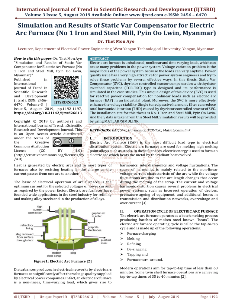
The electric arc furnace operates as a batch melting process
producing batches of molten steel known “heats”. The
electric arc furnace operating cycle is called the tap-to-tap
cycle and is made up of the following operations:
Furnace charging
Melting
Refining
De-slagging
Tapping and
Furnace turn-around.
Figure1: Electric Arc Furnace [2]
Disturbances produces in electrical networks by electric arc
furnaces can significantly affect the voltage quality supplied
by electrical power companies. In fact, an electric arc furnace
is a non-linear, time-varying load, which gives rise to
@ IJTSRD
|
Unique Paper ID – IJTSRD26613
harmonics, inter-harmonics and voltage fluctuations. The
cause of harmonics is mainly related to the non-linear
voltage-current characteristic of the arc while the voltage
fluctuations are due to the arc length changes that occur
during the melting of the scrap. The current and voltage
harmonic distortion causes several problems in electrical
power systems, such as incorrect operation of devices,
premature ageing of equipment, and additional losses in
transmission and distribution networks, overvoltage and
over current [3].
|
Modern operations aim for tap-to-tap time of less than 60
minutes. Some twin shell furnace operations are achieving
tap-to-tap times of 35 to 40 minutes [2].
Volume – 3 | Issue – 5
|
July - August 2019
Page 1192
International Journal of Trend in Scientific Research and Development (IJTSRD) @ www.ijtsrd.com eISSN: 2456-6470
III.
STATIC VAR COMPENSATOR
The Static Var Compensator (SVC) is regarded as the first
FACTS (Flexible AC Transmission System) devices. The SVC
has become known for its ability to offer voltage stability to
the power system and to compensate reactive loads.
However, the SVC does not provide a means for controlling
real power flow directly. It is important to ensure that the
static compensators are switched at the appropriate times so
that transients do not occur. For both capacitors and
inductors, the appropriate switching times occur at the zero
crossing of the current [2].
The first strategy is feed forward control, which repeatedly
solves modelled equations to determine the optimum
inductor firing angle and the number of capacitor and
inductor size needed. Feed forward control is a good choice
when performing load compensation because at any time the
load characteristics can be measured and the optimum
compensating susceptance can be calculated.
The second strategy, feedback control, is useful for closedloop control when minimization of error signals is the
primary goal. Feedback control is useful when terminal
voltages are being maintained because the error signal can
represent the difference between a desired voltage and an
actual voltage. Any change in the error signal will result in a
change in the susceptance of the compensator. The
controllable susceptance of the inductor (BL) can be defined
as a function of the conduction angle and the reactance of the
inductor (XL). The conduction angle σ, opposite from the
firing angle α, is defined as the time that the thyristors are
tuned on.
IV.
SVC CONFIGURATIONS
Controlled reactive power compensation in electric power
systems is usually achieved with the following
configurations:
Thyristor controlled reactor, Fixed capacitor (TCR_FC)
Thyristor controlled reactor, Thyristor switched
capacitor (TCR_TSC)
Thyristor controlled reactor, Mechanically switched
capacitor (TCR_MSC)
Thyristor switched reactor, Thyristor switched
capacitor (TSR_TSC)
V.
MATLAB BASED MODELING ELECTRIC ARC
FURNACE (EAF)
The power quality means voltage quality for this work and to
enhance the power quality. Voltage stability problems
usually encounter in heavily loaded systems. EAF is
operating to melt down the scrap in a moment. During
melting cases, generally, the system voltage decreased from
the constant level. If the running condition stopped, the
voltage will suddenly rise. The main purpose of this chapter
is building simulation model of static var compensator by
using one of programs for modeling called MATLAB and
specially part of MATLAB program called SimPowerSystems
and analyzing the simulation results. This chapter is
specially oriented on static var compensator model which is
used in SimPowerSystems as part application in MATLAB
program. A simplified single line diagram of the main
components in No. 1 Iron and Steel Mill is shown in Figure 2.
@ IJTSRD
|
Unique Paper ID – IJTSRD26613
|
Figure2. Single Line Diagram of No. 1 Iron and Steel Mill
VI.
BASIC ARRANGEMENT
The compensator is a thyristor controlled reactor (TCR) with
thyristor switched capacitor (TSC).The compensator is
connected to the system through 8 MVA, 33 kV/11 kV step
down transformer. On secondary side, reactor bank rated
22.7534 mH of TCR is paralleled with the capacitor bank
rated 222.6504 μF of TSC. The rating of the reactor bank
and capacitor bank may be variable. Moreover, 22.7534 mH
of reactor bank and 222.6504 μF of capacitor bank rating is
the most suitable for Electric Arc Furnace in No. 1 Iron and
Steel Mill.
VII.
COMPONENTS OF STATIC VAR COMPENSATOR
The static var compensator (SVC) is a shunt device of the
flexible AC transmission systems (FACTS) family using
power electronics to control power flow and improve
transient stability on power grids. The SVC regulates voltage
at its terminals by controlling the amount of reactive power
injected into or absorbed from the power system. A static var
compensator (SVC) is used to regulate voltage on 11kV,
8MVA system for Electric Arc Furnace in No. 1 Iron and Steel
Mill. When system voltage is low, the SVC generates reactive
power (SVC capacitive).
When system voltage is high, it absorbs reactive power (SVC
inductive). The variation of reactive power is performed by
switching three-phase capacitor bank and inductor bank
connected on the secondary side of a coupling transformer.
Reactors are either switched on and off TCR. Each capacitor
bank is switched on and off by three thyristor switches TSC.
VIII.
SIMULATION OF ELECTRIC ARC FURNACE
BEFORE USING SVC (TCR-TSC)
In this work No. 1 Iron and Steel Mill in Pyin Oo Lwin is
composed of the various departments, namely Electric Arc
Furnace (EAF), Ladle Refining Furnace (LRF), Continuous
Casting Machine (CCM), Water Treatment Plant (WTP),
Fumes Treatment Plant (FTP), Air Separation Plant (ASP),
Wire Production Plant, Air Compressor, Bolt Nut and
Shredder. Among these departments, EAF is studied as
research area. FFT Analysis is used to know the THD.
Function block of load (EAF) is shown in Figure 3. The
Simulink block diagram of EAF before using SVC is described
in Figure 4. The results of EAF before using static var
compensator are shown in Figure 5 and Fig. 6.
Volume – 3 | Issue – 5
|
July - August 2019
Page 1193
International Journal of Trend in Scientific Research and Development (IJTSRD) @ www.ijtsrd.com eISSN: 2456-6470
Figure3 Function Block of Load (EAF)
Figure7. Total Harmonic Distortion of EAF before
Using SVC
IX.
Figure4 Simulink Block Diagram of EAF before Using
SVC
SIMULATION OF ELECTRIC ARC FURNACE AFTER
USING SVC (TCR-TSC)
After using static var compensator (SVC) for electric arc
furnace are described in the following. Switching the TSC in
and out allows a discrete variation of the secondary reactive
power from zero to 222.6504 μF capacitive at 11 kV,
whereas phase control of the TCR allows a continuous
variation from zero to 22.7534 mH inductive. Moreover, the
SVC is in voltage control mode and its reference voltage is set
to Vref = 1.0 pu. The voltage droop of the regulator is 0.01 pu/
100 VA. The Simulink block diagram of EAF after using SVC
is described in Figure 8.
Figure5 Simulation Results of Source Voltage and
Current before Using SVC
When the electric arc furnace is operating with every load of
steel mill on condition without static var compensator, the
condition of source voltage and current waveforms before
using SVC are shown in Figure 4. And, the condition of load
voltage and current waveforms before using SVC are shown
in Figure 5. Regarding to Figure 4 and Figure 5, voltage and
current waveforms are too much distorted by the effect of
electric arc furnace.
Figure8. Simulink Block Diagram of EAF after Using
SVC
The Static Var Compensator (SVC) regulates voltage on 8
MVA, 11 kV system. The SVC consists of a 33 kV/11 kV,
8MVA step down transformer, 22.7534 mH thyristor
controlled reactor bank (TCR) and 222.6504 μF thyristor
switched capacitor bank (TSC) connected on the secondary
side of the transformer.
Figure6. Simulation Results of Reactive Power before
Using SVC
And then, simulation results of reactive power before using
SVC show in Fig. 5.15. To obtain the desire results, TCR-TSC
type is add to the EAF. Fig. 5.16 shows the simulation result
of harmonics order content and THD percentage. It is clear
that the total harmonics distortion is 67.60%.
@ IJTSRD
|
Unique Paper ID – IJTSRD26613
|
Figure9. Simulation Results of Source Voltage and
Current after Using SVC
Volume – 3 | Issue – 5
|
July - August 2019
Page 1194
International Journal of Trend in Scientific Research and Development (IJTSRD) @ www.ijtsrd.com eISSN: 2456-6470
Figure10. Simulation Results of load Voltage and
Current after Using SV
Figure14. Simulation Results of Alpha for TCR
Figure11. Simulation Results of Reactive Power after
Using SVC
Figure15. Simulation Results of Voltage for TSC
When the electric arc furnace is running with all loads of
steel mill on condition with static var compensator
installation, the status of source voltage and current
waveforms after using SVC are shown in Figure 9. And, the
condition of load voltage and current waveforms after using
SVC are shown in Figure 10.
Figure16. Simulation Results of Thyristor Voltage for
TSC
Figure12. Simulation Results of Voltage and Current
for TCR
Figure17. Simulation Results of Current for TSC
Figure13. Simulation Results of Pulses for TCR
@ IJTSRD
|
Unique Paper ID – IJTSRD26613
|
Volume – 3 | Issue – 5
|
July - August 2019
Page 1195
International Journal of Trend in Scientific Research and Development (IJTSRD) @ www.ijtsrd.com eISSN: 2456-6470
Figure18. Simulation Results of Pulses for TSC
Figure21. Simulation Results of Source Voltage and
Current after Using SVC and Passive Filter
Figure19. Total Harmonic Distortion of EAF after
Using SVC
Moreover, simulation results for TCR are shown in Figure 12,
Figure 13 and Figure 14. And then, Figure 15, Figure 16,
Figure 17 and Figure 18 are simulation results for TSC. From
the simulation results of Figure 19, the percentage of total
harmonic distortion (THD) is 12.56%. It is not existing
within acceptable level by comparing IEEE Standard 519. So,
depending on the harmonic spectrum, the passive filters
designed are low pass filter tuned for 2nd order harmonic
frequency. The subsystem named shunt filter consists of 2nd
harmonic frequency. Based on the design carried out the
filter component value are L= 16mH, C= 25 μF and R=
Figure22. Simulation Results of load Voltage and
Current after Using SVC and Passive Filter
As shown in Figure 21 and Figure 22, voltage and current
waveforms change to smooth by the effectt of SVC and
passive filter installation.
0.83 .
X.
SIMULATION OF ELECTRIC ARC FURNACE WITH
SVC (TCR-TSC) AND PASSIVE FILTER
The status of source voltage and current waveforms after
using SVC and passive filter are shown in Figure 21. And, the
condition of load voltage and current waveforms after using
SVC are shown in Figure 22.
Figure20. Simulink Block Diagram of EAF after Using
SVC and Passive Filter
@ IJTSRD
|
Unique Paper ID – IJTSRD26613
|
Figure23. Simulation Results of EAF after Using SVC
and Passive Filter
Figure24. Simulation Results for EAF after Using SVC
and Passive Filter
Volume – 3 | Issue – 5
|
July - August 2019
Page 1196
International Journal of Trend in Scientific Research and Development (IJTSRD) @ www.ijtsrd.com eISSN: 2456-6470
Figure25. Total Harmonic Distortion of EAF after
Using SVC and Passive Filter
From the simulation results, Total Harmonic Distortion of
electric arc furnace is reduced to 1.60% shown in Figure 25.
By comparing the IEEE standard value, Total Harmonic
Distortion exists within acceptable level. After simulation of
electric arc furnace with SVC and passive shunt filter, the
combine results of Total Harmonic Distortion percentage
before and after SVC and passive shunt filter are presented
in Table I.
Table I. Comparisons of THD with Different Schemes
for EAF
Total Harmonic
Matlab Simulink Model
Distortion, THD (%)
Before Using SVC
67.60 %
After Using SVC
12.56 %
After Using SVC and Filter
1.60%
And then, comparison of THD is shown in Figure 26. To
demonstrator the performance of these passive filter with
TCR and TSC for electric arc furnace load, these are modeled
in MATLAB environment along with SIMULINK and power
system block set toolboxes. It has been shown that before
the use of SVC for electric arc furnace, the percentage of total
harmonic distortion (THD) is 67.60 %. And then, after the
use of SVC for electric arc furnace, the percentage of total
harmonic distortion (THD) is 12.56 %. Finally, after the use
of the combination of SVC with passive filter, it is clear that
the total harmonic distortion of electric arc furnace is 1.60
%.
XI.
CONCLUSIONS
This paper provides a detailed description of a modern, TCRTSC type Static Var Compensator installed on Electric Arc
Furnace (EAF) in iron and steel mill. The SVC is a controller
for voltage regulation and for maintaining constant voltage
at a bus. SVCs are used to improve voltage regulations,
improve power factor, reduction of voltage and current
unbalances, etc. A model has been developed in
MATLAB/SIMULINK and simulated to verify the results.
Simulation results were obtained before and after the use of
SVC. From the analysis of simulation data, THD is 67.60 %
before using SVC is reduced to 12.56 % after using SVC for
electric arc furnace. And then, THD is reduced to 1.60 % after
using SVC and passive filter for electric arc furnace.
ACKNOWLEDGEMENT
The author is grateful to express her gratitude to all persons
who were directly or indirectly involved towards the
successful completion of this paper.
REFERENCES
[1] Ponovo Power Co., Ltd, Static Var Compensator,
December, 2012, (www.ponovo.com.cn)
[2] Yassir Alhazmi, Allocating Power Quality Monitors in
Electrical Distribution Systems to Measure and Detect
Harmonics Pollution, Canada, 2010.
[3] A. T. Jones, Electric Arc Furance Steelmaking, Nupro
Corporation,
Jeremy, July 2009.
[4] R. C. Dugan, M. F. McGranaghan, S. Santoso, H. W. Beaty,
Electrical Power Systems Quality, second edition,
chapter: 5, Fundamentals of Harmonics, August 2008.
[5] H. B. Mutluer, Design, Implementation and Engineering
Aspects of TCR for Industrial SVC Systems, The Graduate
School of Natural and
Sciences Middle east
Technical University, March 2008.
[6] Alexander, K., Thompson, T. and Marc, P.E, Power
Quality in Electrical Systems, McGraw-Hill Companies,
Inc., (2007).
[7] Francisco C. De La Rosa: Harmonics and Power
Systems, Taylor and Francis Group, LLC, (2006).
Figure26. Percentage of Total Harmonic Distortion
@ IJTSRD
|
Unique Paper ID – IJTSRD26613
|
Volume – 3 | Issue – 5
|
July - August 2019
Page 1197


