International Journal of Trend in Scientific Research and Development (IJTSRD)
Volume: 3 | Issue: 4 | May-Jun 2019 Available Online: www.ijtsrd.com e-ISSN: 2456 - 6470
Monitoring and Controlling Device for Smart
Greenhouse by using Thinger.io IoT Server
Win Sandar Aung, Saw Aung Nyein Oo
Department of Electronic Engineering, Mandalay Technological University, Mandalay, Myanmar
How to cite this paper: Win Sandar
Aung | Saw Aung Nyein Oo "Monitoring
and Controlling Device for Smart
Greenhouse by using Thinger.io IoT
Server" Published in International
Journal of Trend in Scientific Research
and Development
(ijtsrd), ISSN: 24566470, Volume-3 |
Issue-4, June 2019,
pp.1651-1656, URL:
https://www.ijtsrd.c
om/papers/ijtsrd25
IJTSRD25212
212.pdf
Copyright © 2019 by author(s) and
International Journal of Trend in
Scientific Research and Development
Journal. This is an Open Access article
distributed under
the terms of the
Creative Commons
Attribution License (CC BY 4.0)
(http://creativecommons.org/licenses/
by/4.0)
ABSTRACT
Smart greenhouse system will be convenient way to get the data from
greenhouse. IoT will provide all work done and information update and current
status of the greenhouse to the person from anywhere and at anytime.
Greenhouse production mainly human force and production capacity is low. The
greenhouse information which the owner gets is limited and the process is time
consuming but real time. Using Iot based on smart greenhouse can quickly obtain
to monitor greenhouse environment data such as humidity, temperature and
light intensity, real time and accurate. Various sensors sense and collect
information to transmit the background processing centre, after analysis can be
precise, can be used both manual and automated control system. The results of
the system are simulated with the help of Proteus simulation software. And the
experimental result evaluation of the implemented control system for
greenhouse is based on the environmental factors of orchids, the propose plant
grown in smart greenhouse. Orchids are expensive products in plant market. So
orchids are chosen to grow in the smart greenhouse.
Keywords: Arduino, nodeMCU, proteus software ,thinger.io cloud server
I.
INTRODUCTION
With the rapid development of electronic and agricultural technology research
and their applications have been paid more and more attention, especially the
greenhouse has become an important role. Greenhouse is a said to be a place that
creates the best conditions for plant growth, can change plant growth and avoid
influence on plant growth due to outside changing seasons and severe weather
[1].
The optimum condition of plant growth is obtained on the
basis of taking full use of natural resources by changing
greenhouse environment factors such as temperature,
humidity, light, and water concentration.
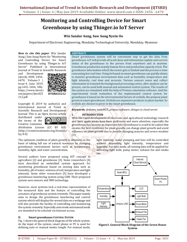
light intensity, water pumping and fans will be controlled
without depending light intensity, temperature and
humidity. For auto mode, all sensing data will be applied for
activating light bulb, pump motor, exhaust fan and intake
fan.
Several authors have proposed using IOT concept in
agriculture [2] and greenhouse [3]. Some researchers [4]
have described an embedded system approach for
monitoring greenhouse based on sensing data such as
humidity, pH of water, wetness of soil, temperature and light
intensity. Some other researchers [5] have developed a
greenhouse monitoring system using GSM. Their proposed
system uses sensors and SMS technology.
However, most systems lack a real-time representation of
the measured data and the feature of controlling the
actuators of greenhouse system remotely. This paper mainly
aims to design the greenhouse monitoring and control
system which will display the sensed data on a webpage and
will also provide the facility of controlling and monitoring
the system remotely. Especially auto mode and manual mode
are intended to be selected via Internet access.
II.
Smart greenhouse CONTROL SYSTEM
Fig. 1 shows the general block diagram of the whole system.
As the input of the system, smart phone or PC is used for
defining auto or manual modes length. For manual mode,
@ IJTSRD
|
Unique Paper ID – IJTSRD25212
|
Figure1. General Block Diagram of the Green House
System
Volume – 3 | Issue – 4
|
May-Jun 2019
Page: 1651
International Journal of Trend in Scientific Research and Development (IJTSRD) @ www.ijtsrd.com eISSN: 2456-6470
III.
Substituting R from equation 1 into equation 2, the light
intensity can be calculated using the following formula.
OVERALL CIRCUIT DESIGN
(3)
Figure5. Light Dependence Resistor
Figure2. Overall Circuit Diagram
Figure3. 24V 0.19A 2200 Rpm Fan 24V low power fans
are used for exhaust and intake fans as shown in fig 3.
Figure6. Voltage Divider Circuit for Measuring Light
Intensity
Moreover, Arduino UNO gives 10 bit resolution or 1024 ADC
values for 5V range. The following equation can be applied
for ADC to Vo conversion.
(4)
Figure4. 12V DC Pump Motor 350ma
For pumping system 12V DC pump motor (in fig 4) is applied
and it can only draw 350mA current maximum. IRFZ44N Nchannel MOSFET has 55V VDSS and 49A ID maximum rating. It
can drive fans and pump motor easily. For light bulb, ac
supply and relay drive is applied. Necessary DC voltage
levels are regulated from 220:24V step down transformer.
IV.
FUNCTIONAL DESCRIPTION
A. Light Intensity Sensing
The resistance of the Light Dependence Resistor (LDR)
varies according to the amount of light that falls on it. The
relationship between the resistance R and light intensity for
a typical LDR is
(1)
B. Temperature and Humidity Sensing
DHT11 Temperature & Humidity Sensor features a
temperature & humidity sensor complex with a calibrated
digital signal output. By using the exclusive digital-signalacquisition technique and temperature and humidity sensing
technology, it ensures high reliability and excellent longterm stability. This sensor includes a resistive-type humidity
measurement component and an NTC temperature
measurement component, and connects to a high
performance 8-bit microcontroller, offering excellent quality,
fast response, anti-interference ability and costeffectiveness.
If the LDR connected to 5V through a 10 kΩ resistor as
shown in fig 6, using voltage divider rule, the output voltage
of LDR is
(2)
@ IJTSRD
|
Unique Paper ID – IJTSRD25212
|
Volume – 3 | Issue – 4
Figure7. DHT11 Sensor
|
May-Jun 2019
Page: 1652
International Journal of Trend in Scientific Research and Development (IJTSRD) @ www.ijtsrd.com eISSN: 2456-6470
The single-wire serial interface makes system integration
quick and easy. Its small size, low power consumption and
up-to-20 meter signal transmission making it the best choice
for Arduino UNO. Moreover measurable range goes for 2090% humidity and 0-50 Celsius which is enough for green
house application.
At the beginning of the system, Serial communication with
9600 bit per second transfer rate is applied between
NodeMCU and Arduino. Reading Serial command, the system
will distinct “auto mode” or “manual mode”. For auto mode,
all sensing data will be applied for activating loads. When
humidity goes less than 50%, pump motor will be driven,
and the system allows intake fan ON for blowing out inside
wet air when humidity reaches over 80%. When inside
temperature exceeds 40 degree Celsius, exhaust fan will be
activated for cooling. Light intensity level of 10763 Lux is
defined as minimum and whenever it goes low, the light bulb
will be activated too.
For manual mode, direct command from Internet access is
applied. And mode selecting will be done using Internet
access too.
Figure8. Timing Diagram of DHT11 Data Transfer
Single-bus data format is used for communication and
synchronization between Arduino and DHT11 sensor. One
communication process is about 4ms. Data consists of
decimal and integral parts. A complete data transmission is
40bit, and the sensor sends higher data bit first.
Data format: 8bit integral RH data + 8bit decimal RH data +
8bit integral T data + 8bit decimal T data + 8bit check sum. If
the data transmission is right, the check-sum should be the
last 8bit of "8bit integral RH data + 8bit decimal RH data +
8bit integral T data + 8bit decimal T data". Fig 8 represents
the timing diagram for requestion from Arduino and signal
feedback from sensor with 80 µs long bit size.
C. NodeMCU
Figure10. Program Flowchart of Nodemcu and
Arduino Uno
Figure9. NODEMCU using ESP8266
For Internet access, NodeMCU shown in fig 9 is applied to
connect existing WiFi. It is an open source Lua based
firmware for the ESP8266 WiFi SOC from Espressif and uses
an on-module flash-based SPIFFS file system. NodeMCU is
implemented in C and is layered on the Espressif NON-OS
SDK [6]. The firmware was initially developed as is a
companion project to the popular ESP8266-based NodeMCU
development modules, but the project is now communitysupported, and the firmware can now be run on any ESP
module. ESP8266 is integrated with a 32-bit Tensilica
processor, standard digital peripheral interfaces, antenna
switches, RF balun, power amplifier, low noise receive
amplifier, filters and power management modules.
UPLOADING AND RETRIEVING SENSING DATA
V.
For using IoT service, thinger.io cloud is used. Firstly,
thinger.io account is created and logged in this account.
Statistics section can be accessed as the default which can
be seen some basic information about this account , like
devices, endpoint, data buckets, dashboard and so on and
shown in fig 11.
D. Control Program Development
Using Arduino IDE and NodeMCU plugin, two programs was
developed. The first one is embedded in NodeMCU for data
transfer between Internet and Arduino. The second one
stands for sensor reading, load controlling and connecting
with Node MCU. These two program can be expressed the
following flowchart shown in fig 10.
Figure11. Console Dashboard
@ IJTSRD
|
|
Unique Paper ID – IJTSRD25212
|
Volume – 3 | Issue – 4
May-Jun 2019
Page: 1653
International Journal of Trend in Scientific Research and Development (IJTSRD) @ www.ijtsrd.com eISSN: 2456-6470
Fig 12 is how the Smart Greenhouse connects with the thinger.io cloud server.
Figure12. Connecting the Device and Cloud
VI.
EXPERIMENTAL TEST AND RESULT
The program is written using Arduino IDE and thinger.io and the I2C LCD is applied for debugging in Proteus Simulation. By
testing with simulation, control sequence, sensing data and actuator driver can be tested. Auto and manual control mode can be
chosen from the PC or mobile phone. For choosing auto mode, the simulation result is shown the following Figures. Fig 13
shows that pump is ON when the humidity level is less than the threshold value.
.
Figure13. Simulation result for pump is ON
Fig 14 shows that input fan is On when humidity level is more than the threshold value. When the temperature and illumination
level are less than the threshold value, output fan and lighting system are ON.
Figure14. Simulation Result for Lighting, Input and Output Fan are ON
@ IJTSRD
|
Unique Paper ID – IJTSRD25212
|
Volume – 3 | Issue – 4
|
May-Jun 2019
Page: 1654
International Journal of Trend in Scientific Research and Development (IJTSRD) @ www.ijtsrd.com eISSN: 2456-6470
Humidity level, temperature level and light intensity can be monitored in thinger.io cloud from anywhere and at anytime as
shown in following fig 15, 16, 17.
Figure15. Monitoring the Humidity Level
Figure16. Monitoring the Temperature Level
Figure17. Monitoring the light intensity level
And if manual mode is also chosen, the actuators are controlled from the PC or mobile phone as shown in fig 18.
Figure18. Controlling the actuators from mobile phone
@ IJTSRD
|
Unique Paper ID – IJTSRD25212
|
Volume – 3 | Issue – 4
|
May-Jun 2019
Page: 1655
International Journal of Trend in Scientific Research and Development (IJTSRD) @ www.ijtsrd.com eISSN: 2456-6470
VII.
CONCLUSION
The proposed IoT based greenhouse monitoring system is a
complete system designed to monitor and control the
environmental parameters inside a greenhouse for small
plants or flowers like orchid. The traditional system for
greenhouse monitoring is labor intensive and time
consuming. The proposed system saves time, money and
human effort. According to Internet access, it can be
controlled and monitored from anywhere in the world. It
provides a controlled environment for the plants to prevent
them from damage and thus increasing the analytical study
about plants and flower in the field of biotechnology. The
smart greenhouse automatically or manually controls the
various parameters needed for the plants and sends the
sensory data to a customized webpage for continuous and
effective monitoring.
ACKNOWLEDGMENT
The author would like to thank Dr. Tin Tin Hla, Head of the
Department of Electronics Engineering, Mandalay
Technological University, for her kind advice and
encouragement. Special thanks are due to her supervisor: Dr.
Saw Aung Nyein Oo, Associate Professor, Department of
Electronics Engineering and also thank all the teachers from
the Department of Electronics Engineering, Mandalay
Technological University. Finally, the author deeply grateful
express to her parents and family members for their support
and encouragement her during this research.
@ IJTSRD
|
Unique Paper ID – IJTSRD25212
|
REFERENCES
[1] Iris Wieser, "Autonomous Robotic SLAM-based Indoor
Navigation for High Resolution Sampling with
Complete Coverage", conference paper IEEE, 2014
[2] Ji-chun Zhao, Jun-feng Zhang, Yu Feng, Jian-xin Guo,
“The Study and Application of the IOT Technology in
Agriculture”, Computer Science and Information
Technology (ICCSIT), 2010 3rd IEEE International
Conference, 9-11 July 2010.
[3] Cui Wenshun, Cui Shuo, Yuan Lizhe, Shang Jiancheng,
“Design and implementation of sunlight greenhouse
service platform based on IOT and cloud computing”,
2nd International Conference on Measurement,
Information and Control (ICMIC), August 2013, Vol. 01,
pp. 141-144.
[4] Rangan K. and T. Vigneswaran, “An Embedded systems
approach to monitor greenhouse”, IEEE Conference on
Recent Advances in Space Technology Services and
Climate Change (RSTSCC), 2010, pp. 61-65.
[5] Prakash. H. Patil, Chaitali Borse, Snehal Gaikwad and
Shilpa Patil, “Greenhouse Monitoring System Using
GSM”, International Journal of Scientific & Engineering
Research, 2013, Vol. 4, Issue 6.
[6] https://nodemcu.readthedocs.io/en/master/
Volume – 3 | Issue – 4
|
May-Jun 2019
Page: 1656


