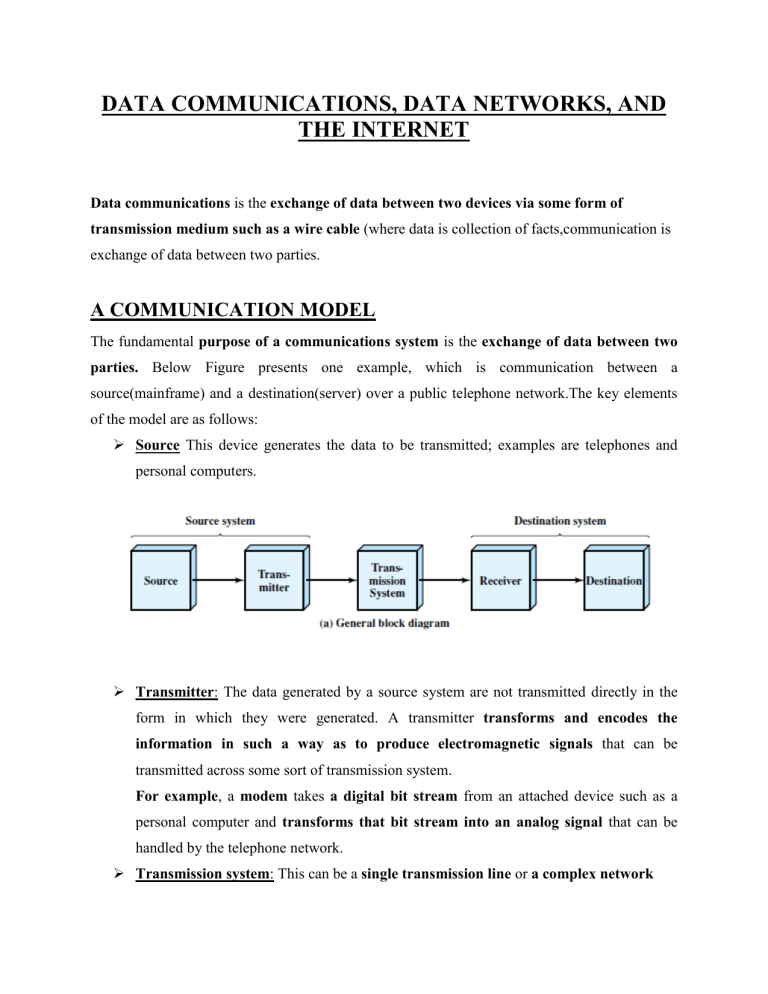
DATA COMMUNICATIONS, DATA NETWORKS, AND THE INTERNET Data communications is the exchange of data between two devices via some form of transmission medium such as a wire cable (where data is collection of facts,communication is exchange of data between two parties. A COMMUNICATION MODEL The fundamental purpose of a communications system is the exchange of data between two parties. Below Figure presents one example, which is communication between a source(mainframe) and a destination(server) over a public telephone network.The key elements of the model are as follows: Source This device generates the data to be transmitted; examples are telephones and personal computers. Transmitter: The data generated by a source system are not transmitted directly in the form in which they were generated. A transmitter transforms and encodes the information in such a way as to produce electromagnetic signals that can be transmitted across some sort of transmission system. For example, a modem takes a digital bit stream from an attached device such as a personal computer and transforms that bit stream into an analog signal that can be handled by the telephone network. Transmission system: This can be a single transmission line or a complex network connecting source and destination. Receiver: The receiver accepts the signal from the transmission system and converts it into a form that can be handled by the destination device. For example, a modem will accept an analog signal coming from a network or transmission line and convert it into a digital bit stream. Destination: Takes the incoming data from the receiver. The Communication tasks or key tasks that must be performed in a data communications system are listed below. The first, transmission system utilization, refers to the need to make efficient use of transmission facilities that are typically shared among a number of communicating devices. Various techniques (referred to as multiplexing) are used to allocate the total capacity of a transmission medium among a number of users. Congestion control techniques may be required to assure that the system is not overwhelmed by excessive demand. To communicate, a device must interface with the transmission system. Electromagnetic signals are propagated over a transmission medium. Once an interface is established, signal generation is required for communication. The properties of the signal, must be such that the signal is (1) capable of being propagated through the transmission system, and (2) interpretable as data at the receiver. There must be some form of synchronization between transmitter and receiver. The receiver must be able to determine when a signal begins to arrive and when it ends. It must also know the duration of each signal element. Exchange management If data are to be exchanged in both directions over a period of time, the two parties must cooperate. For example, for two parties to engage in a telephone conversation, one party must dial the number of the other, causing signals to be generated that result in the ringing of the called phone. The called party completes a connection by lifting the receiver. In all communications systems, there is a potential for error; transmitted signals are distorted to some extent before reaching their destination. Error detection and correction are required in circumstances where errors cannot be tolerated. For example, in transferring a file from one computer to another, it is simply not acceptable for the contents of the file to be accidentally altered. Flow control is required to assure that the source does not overwhelm the destination by sending data faster than they can be processed and absorbed. Addressing When more than two devices share a transmission facility, a source system must indicate the identity of the intended destination. The transmission system must assure that the destination system, and only that system, receives the data. Routing The transmission system may itself be a network through which various paths may be taken. A specific route through this network must be chosen to reach the destination. Recovery is a concept distinct from that of error correction. Recovery techniques are needed in situations in which an information exchange, such as a database transaction or file transfer, is interrupted due to a fault somewhere in the system. The objective is either to be able to resume activity at the point of interruption or at least to restore the state of the systems. Message formatting has to do with an agreement between two parties as to the form of the data to be exchanged or transmitted, such as the binary code for characters. Security The sender of data may wish to be assured that only the intended receiver actually receives the data(confidentiality). And the receiver of data may wish to be assured that the received data have not been altered in transit and that the data actually come from the purported sender(authentication). Network management capabilities are needed to configure the system, monitor its status, react to failures and overloads, and plan intelligently for future growth. A DATA COMMUNICATIONS MODEL The input device and transmitter are components of a personal computer.The user of the PC wish to send a message m to another user. The user activates the electronic mail package on the PC and enters the message via the keyboard (input device). The character string is briefly buffered in main memory as a sequence of bits (g).The personal computer is connected to some transmission medium, by an I/O device transceiver or a modem. The input data are transferred to the transmitter as a sequence of voltage shifts [g(t)] representing bits on some communications bus or cable. Figure 1.3 shows a Simplified Data Communications Model. The transmitter is connected directly to the medium and converts the incoming stream [g(t)] into a signal [s(t)] suitable for transmission. The transmitted signal s(t) presented to the medium is subject to a number of impairments before it reaches the receiver. Thus, the received signal r(t) may differ from s(t). The receiver will attempt to estimate the original s(t), based on r(t), producing a sequence of bits g’(t). These bits are sent to the output personal computer, where they are buffered in memory as a block of bits (g’). In many cases, the destination system will attempt to determine if an error has occurred if so; cooperate with the source system to eventually obtain a complete, error-free block of data. These data are then presented to the user via an output device, such as a printer or screen. The message as viewed by the user will usually be an exact copy of the original message (m). Consider a telephone conversation. In this case the input to the telephone is a message (m) in the form of sound waves. The sound waves are converted by the telephone into electrical signals of the same frequency. These signals are transmitted without modification over the telephone line. Hence the input signal g(t) and the transmitted signal s(t) are identical. The signals (t) will suffer some distortion over the medium, so that r(t) will not be identical to s(t). Nevertheless, the signal r(t) is converted back into a sound wave with no attempt at correction or improvement of signal quality. Thus, m’ is not an exact replica of m. However, the received sound message is generally comprehensible to the listener. NOTE: 1. The two major approaches to increase the efficiency of transmission medium are multiplexing and compression. Multiplexing refers to the ability of a number of devices to share a transmission facility. Compression, as the name indicates, involves squeezing the data down so that a lowercapacity, cheaper transmission facility can be used to meet a given demand. 2. Data rates that can be achieved & rate at which errors can occur depend on the nature of the signal & type of the medium. Ex: data rate of Tranmission medium like optical fibre or wireless communication is high compared to twisted pair or coaxial cable. 3. Communication Techniques or Encoding techniques used also affects performance & reliability. NETWORKS A network is a set of devices (often referred to as nodes) connected by communication links in order to share resource(hardware or software). A node can be a computer,or any other device capable of sending and/or receiving data generated by other nodes on the network. Types of Networks: Networks are categorized as LAN or WAN based on the size of the network. Local area networks A LAN is a communications network that interconnects a variety of devices and provides a means for information exchange among those devices. i. A local area network (LAN) is usually privately owned and links the devices in a single office, building, or campus. ii. Currently, LAN size is limited to a few kilometers. iii. LANs are designed to allow resources to be shared between personal computers. The resources to be shared can include hardware (e.g., a printer), software (e.g., an application program), or data. iv. Early LANs had data rates in the 4 to 16 megabits per second (Mbps) range. Today, however, speeds are normally 100 or 1000 Mbps. v. The most common are switched LANs and wireless LANs. vi. The most common switched LAN is a switched Ethernet LAN, which may consist of a single switch with a number of attached devices, or a number of interconnected switches. Wireless LANs use a variety of wireless transmission technologies and organizations. vii. There are several key distinctions between LANs and WANs: 1. The scope of the LAN is small, typically a single building or a cluster of buildings. 2. The internal data rates of LANs are typically much greater than those of WANs. Wide Area Networks A wide area network (WAN) provides transmission of data over large geographic areas that may comprise a country, a continent, or even the whole world. A WAN consists of a number of interconnected switching nodes. A transmission from any one device is routed through these internal nodes to the specified destination device. WANs have been implemented using one of two technologies: circuit switching and packet switching. More recently, frame relay and ATM networks have assumed major roles. Circuit Switching In a circuit-switching network, a dedicated communications path is established between two stations through the nodes of the network. That path is a connected sequence of physical links between nodes. i. On each link, a logical channel is dedicated to the connection. ii. Data generated by the source station are transmitted along the dedicated path as rapidly as possible. iii. At each node, incoming data are routed or switched to the appropriate outgoing channel without delay but may lead to congestion. Packet Switching Data is not sent along a dedicated path through the network. i. Data are sent out in a sequence of small chunks, called packets. ii. Each packet is passed through the network from node to node along some path leading from source to destination. iii. At each node, the entire packet is received, stored briefly, and then transmitted to the next node. iv. Packet-switching networks were designed with a data rate to the end user of about 64 kbps Frame Relay There is a considerable amount of overhead built into packet-switching schemes to compensate for errors(error detection). The overhead includes additional bits added to each packet to introduce redundancy and additional processing at the end stations and the intermediate switching nodes to detect and recover from errors. With modern high-speed telecommunications systems, this overhead is unnecessary. i. Frame relay was developed to take advantage of these high data rates and low error rates. ii. Frame relay uses variable-length packets, called frames, iii. Frame relay networks are designed to operate efficiently at user data rates of up to 2 Mbps. iv. The key to achieving these high data rates is to strip out most of the overhead involved with error control. ATM(Asynchronous transfer mode) also referred to as cell relay. i. It is a culmination of developments in circuit switching and packet switching. ii. ATM can be viewed as an evolution from frame relay and ATM uses fixed-length packets, called cells. iii. ATM provides little overhead for error control. iv. The result is that ATM is designed to work in the range of 10s and 100s of Mbps, and in the Gbps range. v. By using small, fixed-size cells, ATM is so efficient that it can offer a constant-data-rate channel even though it is using a packet-switching technique. vi. ATM extends circuit switching to allow multiple channels with the data rate on each channel dynamically set on demand. INTERNET:Internet is used to connect two or more networks. Ex: Two or more LAN’s. Origins of the Internet The Internet evolved from the ARPANET, which was developed in 1969 by the Advanced Research Projects Agency (ARPA) of the U.S. Department of Defense. It was the first operational packet-switching network. Key Elements Figure 1.4 illustrates the key elements that comprise the Internet. The purpose of the Internet is to interconnect end systems, called hosts; these include PCs, workstations, servers, mainframes, and so on. Most hosts that use the Internet are connected to a network, such as a local area network (LAN) or a wide area network (WAN). These networks are in turn connected by routers. Router is a networking device that forwards data from one network to another network until it reaches destination node i.e., Each router, as it receives a packet, makes a routing decision and forwards the packet along its way to the destination. The Internet operates as follows. A host may send data to another host anywhere on the Internet. The source host breaks the data to be sent into a sequence of packets, called IP datagrams or IP packets. Each packet includes a unique numeric address of the destination host. This address is referred to as an IP address, because the address is carried in an IP packet. Based on this destination address, each packet travels through a series of routers and networks from source to destination. Internet Architecture: Key element of the internet is the set of hosts attached to it. Individual hosts and LANs are connected to an Internet service provider (ISP) to access the internet through a POP(point of presence),where connections from users are accepted & authenticated . The connection is made in a series of steps starting with the customer premises equipment (CPE).The CPE is the communications equipment located onsite with the host. The CPE is physically attached to the “local loop”.This is the infrastructure between a provider’s installation and the site where the host is located. For example, a home user with a 56K modem attaches the modem to the telephone line. The telephone line is typically a pair of copper wires that runs from the house to a central office (CO) of ISP owned and operated by the telephone company. In this instance the local loop is the pair of copper wires running between the home and the CO. The ISP acts as a gateway to the Internet, providing many important services. For most home users, the ISP provides the unique numeric IP address needed to communicate with other Internet hosts. Physical access can be implemented from different ISPs. The network access point (NAP) mechanism is used for this purpose. A NAP is a physical facility that provides the infrastructure to move data between connected networks(ISP’s). The networks connected at a NAP are owned and operated by network service providers (NSPs). NOTE: Hierarchical organization of the Internet a. Structure of a national ISP Regional Internet Service Providers Regional internet service providers or regional ISPs are smaller ISPs that are connected to one or more national ISPs. Local Internet Service Providers Local Internet service providers provide direct service to the end users. The local ISPs can be connected to regional ISPs or directly to national ISPs. Most end users are connected to the local ISPs.


