Pile Spacing (PPA and Technical Standard and Commentaries for Port and Harbor Facilities in Japan)
advertisement

l
r
l
f
Consideration of Pile Group Action
L
When piles are used as a pile group, the effect of pile group action on the
behavior of individual piles shall be considered.
r
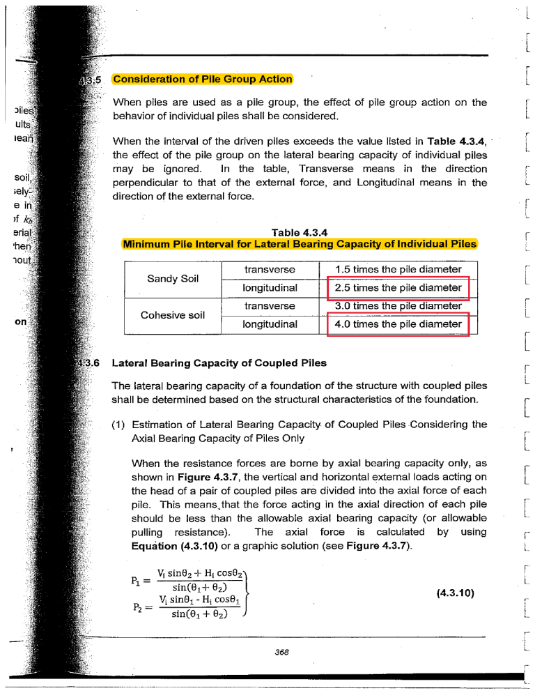
When the inteNal of the driven piles exceeds the
the effect of the pile group on the lateral bearing
may be ignored.
In the table, Transverse
perpendicular to that of the external force, and
direction of the external force.
L
r
value listed in Table 4.3.4, .
capacity of individual piles
means in the direction
Longitudinal means in the
j
L
r
L
,-
.
l
Table 4.3.4
Minimum Pile Interval for Lateral Bearing Capacity of Individual Piles
transverse
1.5 times the pile diameter
longitudinal
2.5 times the pile diameter
transverse
3.0 times the pile diameter
longitudinal
4.0 times the pile diameter
Sandy Soil
Cohesive soil
i
~
!
L
Lateral Bearing Capacity of Coupled Piles
r
The lateral bearing capacity of a foundation of the structure with coupled piles
shall be determined based on the structural characteristics of the foundation.
L
I
[
(1) Estimation of Lateral Bearing Capacity of Coupled Piles Considering the
Axial Bearing Capacity of Piles Only
When the resistance forces are borne by axial bearing capacity only, as
shown in Figure 4.3.7, the vertical and horizontal external loads acting on
the head of a pair of coupled piles are divided into the axial force of each
pile. This meansJhat the force acting in the axial direction of each pile
should be less than the allowable axial bearing capacity (or allowable
pulling resistance).
The axial force is calculated by using
Equation (4.3.10) or a graphic solution (see Figure 4.3.7).
(4.3.10)
!
L
,i
L
L
."
i
L
r'
I
368
L
~.~;~
L ,:'
l
Ii
1('
~;
..
The coefficient of lateral subgrade reaction kh may be calculated by
multiplying the value of kh obtained in (3) (b) in 4.3.4 Estimation of Pile
Behavior Using Analytical Methods by the factor obtained from Figure
4.3.5, in accordance with the inclination of piles.
" '
d
0
0
0
0
0
Table 4.3.5
Spring Constants of Pile Head
Axial spring
constant of pile
head ( Ii! )
[J
Cohesive soil
Friction piles
Sandy soil
Pile head hinged
0
0
0
0
Lateral axial spring
constant of pile
head (f1)
Pile head fixed
[]
4.4.1
0
11
'
Without exposed
section
(1..= 0)
With exposed
section
(Aif' 0)
Without exposed
section
(1..= 0)
With exposed
section
(Aif' 0)
.
4.4
"I",
AE
w= 1..+1
2AE
w= 21..+ 1
3AE
w= 31..+ 21
Bearing piles
3 Es
11=2EI13 = 213
3EI
3
11= A <jlll(13A)
3 Es
11=4EI13 = 13
12EI
11= A3<jlll (131..)
PILE DESIGN IN GENERAL
Load Sharing
(1) Vertical loads shall be supported by piles alone. No capacity shall be
expected for the ground touching with the bottom of structures supported
by piles. Some gap may appear between the bottom of the structure
supported by piles and the ground underneath it as time passes, even if
the bottom is constructed by touching the ground. Thus, for the sake of
safety, the bearing capacity of the ground under a structure should be
ignored.
373
l
[
[
. (2) In principle, horizontal loads shall be supported by piles alone. However,
when enough resistance can be obtained by the earth pressure acting on
the embedded section of structure alone, this resistance may be assumed
to support the horizontal load. In .principle, horizontal loads should be
supported by piles alone. If the resistance due to passive earth pressure·
against the embedded section of structure can be expected, this
resistance may be added. However it is generally difficult to calculate the
resistance due to passive earth pressure in this case. There is no simple
way of determining whether the passive earth pressure of the ground
reaches its ultimate value in response to the pile head displacement
corresponding to the allowable lateral bearing capacity of piles. In some
cases, if a structure is displaced to the extent of passive earth pressure
obtained by using Coulomb's equation, this displacement of the structure
could cause the pile bending failure. These factors must be fully
considered when calculating this resistance due to passive earth pressure
at the embedded section.
r
Ic.
L
[
[
I
L
Load Distribution
I,c_
Within the same foundation, piles shall be arranged so that vertical and
horizontal forces acting on individual piles are as equal as possible.
[
Distance Between Centers of Piles
•..
When determining the distance between the centers of piles to be driven, the
workability, deformation behavior of surrounding ground, and behavior as a
pile group shall be taken into account.
[
,i
Allowable Stresses for Pile Materials
L
c-
Allowable stresses for pile materials shall be determined based on their
characteristics.
I
i,..
[
DETAILED DESIGN
Examination of Loads During Construction
In designing piles, it is recommended to examine not only the loads acting
after completion of construction but also those during transportation,
positioning, and driving.
,c•
L
r
L
374
TECHNICAL STANDARDS AND COMMENTARIES FOR PORT AND HARBOUR FACILITIES IN JAPAN
[5] Consideration of Pile Group Action
(1) When piles are used as a pile group, the effect of pile group action on the behavior of individual piles is necessary
to be considered.
(2) When the center interval of driven piles exceeds the values in Table 2.4.10, the action of the pile group on lateral
resistance may be ignored.
Table 2.4.10 Center Intervals of Piles
Sandy soil
Cohesive soil
Transverse
Pile diameter x 1.5
Longitudinal
Pile diameter x 2.5
Transverse
Pile diameter x 3.0
Longitudinal
Pile diameter x 4.0
[6] Lateral Bearing Capacity of Coupled Piles
(1) The lateral bearing capacity of a foundation of the structure with coupled piles is necessary to be determined as
appropriate in view of structural characteristics of the foundation.
(2) Distribution of Horizontal Force in Foundation with a Combination of Vertical and Coupled Piles
When a horizontal force acts on a foundation with a combination of vertical and coupled piles, the force borne by
vertical piles is far smaller than that borne by coupled piles under the condition of equal horizontal displacement. It may generally be assumed that all of the horizontal force is borne by the coupled piles.
(3) Lateral Bearing Capacity of Coupled Piles
There are two calculation methods for the lateral bearing capacity of coupled piles. The first method only
takes account of the resistance of the axial bearing capacity of each pile. The second method takes account
of the resistance of the axial bearing capacity of each pile as well as the lateral bearing capacity of each pile in
consideration of the bending resistance of piles.
(4) Case when Only Axial Resistance of Individual Piles is Considered as Resisting Horizontal Force
When only the axial resistance is considered as resistance, as shown in Fig. 2.4.19, the vertical and horizontal
actions acting on the head of a pair of coupled piles shall be divided into the axial force of each pile. The coupled
piles shall be designed in a way that the axial force on each pile is less than the design values of the axial resistance
or design values of the axial pulling resistance of the respective piles. The axial force can be calculated using
equation (2.4.46) or a graphic solution (see Fig. 2.4.19)
(2.4.46)
where
P1, P2 :
θ1, θ2 :
Vi :
Hi :
pushing force acting on each pile or pulling force when the value is negative (kN)
inclination angle of each pile (º)
vertical force acting on coupled piles (kN)
horizontal force acting on coupled piles (kN)
– 466 –


