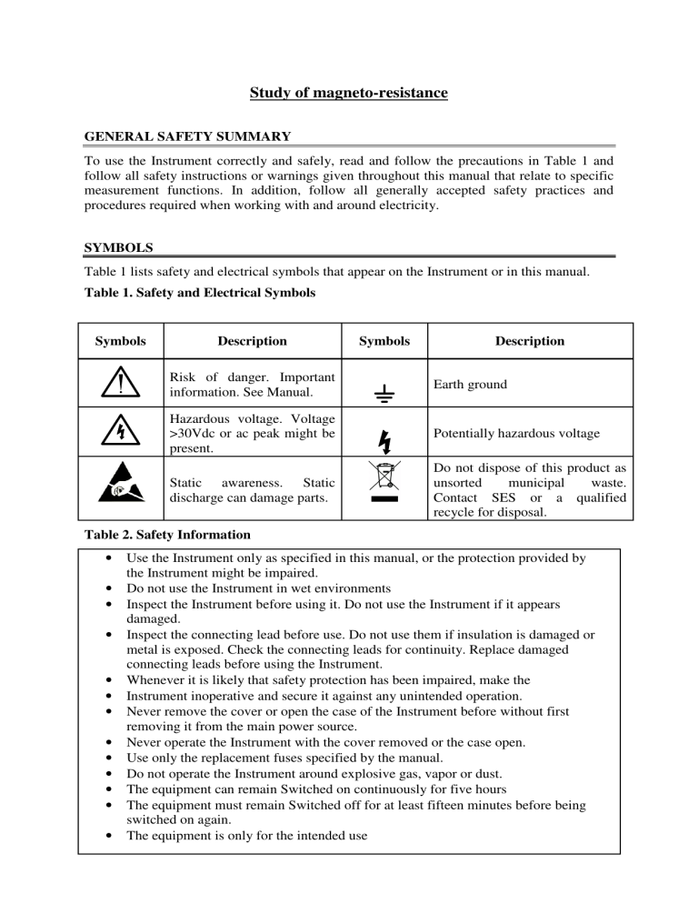
Study of magneto-resistance GENERAL SAFETY SUMMARY To use the Instrument correctly and safely, read and follow the precautions in Table 1 and follow all safety instructions or warnings given throughout this manual that relate to specific measurement functions. In addition, follow all generally accepted safety practices and procedures required when working with and around electricity. SYMBOLS Table 1 lists safety and electrical symbols that appear on the Instrument or in this manual. Table 1. Safety and Electrical Symbols Symbols Description Symbols Description Risk of danger. Important information. See Manual. Earth ground Hazardous voltage. Voltage >30Vdc or ac peak might be present. Potentially hazardous voltage Static awareness. Static discharge can damage parts. Do not dispose of this product as unsorted municipal waste. Contact SES or a qualified recycle for disposal. Table 2. Safety Information • • • • • • • • • • • • • Use the Instrument only as specified in this manual, or the protection provided by the Instrument might be impaired. Do not use the Instrument in wet environments Inspect the Instrument before using it. Do not use the Instrument if it appears damaged. Inspect the connecting lead before use. Do not use them if insulation is damaged or metal is exposed. Check the connecting leads for continuity. Replace damaged connecting leads before using the Instrument. Whenever it is likely that safety protection has been impaired, make the Instrument inoperative and secure it against any unintended operation. Never remove the cover or open the case of the Instrument before without first removing it from the main power source. Never operate the Instrument with the cover removed or the case open. Use only the replacement fuses specified by the manual. Do not operate the Instrument around explosive gas, vapor or dust. The equipment can remain Switched on continuously for five hours The equipment must remain Switched off for at least fifteen minutes before being switched on again. The equipment is only for the intended use Fig.1: Panel Diagram of the magneto-resistance set up Range Selector Switch Current Output Bismuth Sample RANGE Offset Zero Adj. Knob ZERO ADJ Magnetoresistance Probe Hall Probe Stand Voltage Input 1 mV 10 mV 100 mV 1V 10 V Model : DMV-001 200mA Range Switch 20mA CURRENT Model : CCS - 01 DIGITAL MICROVOLTMETER OUTPUT mA On-off Switch ON On-off Switch ON CONSTANT CURRENT SOURCE Zero Adj. Knob Hall Probe InAs GAUSS ON On-off Switch Black Red Red Black Current Display Selector Switch Range Switch RANGE X1 X10 DIGITAL GAUSSMETER Model : DGM-102 COIL1 COIL2 A Down COIL1 COIL2 Current Control Up Model : DPS-175M Mains ON/ OFF Switch ON CONSTANT CURRENT POWER SUPPLY Display Panel Magnetising Current Fuse OBJECTIVES: (I) To determine magneto-resistance of n-Ge (II) To study magneto-resistance of Bi INTRODUCTION It is noticed that the resistance of a sample changes when the magnetic field is turned on. The Magneto-resistance is the property of a material to change the value of its electrical resistance when an external magnetic field is applied to it. The effect was first discovered by William Thomson (more commonly known as Lord Kelvin) in 1856. The magnitude of the effect is quite low only about 1% at room temperature, but goes to about 50% at low temperatures in giant magneto resistive multilayer structures. More recently effects of more than 95% change in resistivity have been discovered in some perovskite systems. Magneto-resistance, is due to the fact that the drift velocity of all the carriers is not same. With the magnetic field on; the Hall voltage V = E y t = v x H compensates exactly the Lorentz force for carriers with average velocity; slower carriers will be over compensated and faster ones undercompensated, resulting in trajectories that are not along the applied field. This results in an effective decrease of the mean free path and hence an increase in resistivity. Here the above referred symbols are defined as: v = drift velocity; E = applied electric field; t = thickness of the crystal; H = Magnetic field The change in resistivity, Δρ, is positive for both magnetic field parallel (Δρll) and transverse (ΔρT) to the current direction with ρT> ρll. There are three distinct cases of ordinary magnetoresistance, depending on the structure of the electron orbitals at the Fermi surface: 1. In metals with closed Fermi surfaces, the electrons are constrained to their orbit in kspace and the effect of the magnetic field is to increase the cyclotron frequency of the electron in its closed orbit. 2. For metals with equal numbers of electrons and holes, the magnetoresistance increases with H up to the highest fields measured and is independent of crystallographic orientation. Bismuth falls in this class. 3. Metals that contain Fermi surfaces with open orbits in some crystallographic directions will exhibit large magnetoresistance for fields applied in those directions, whereas the resistance will saturate in other directions, where the orbits are closed. APPARATUS 1. 2. 3. 4. 5. 6. 7. 8. Four probe arrangement Samples: n-Ge, Bismuth Constant Current Source, CCS-01 Digital Microvoltmeter, DMV-001 Electromagnet, Model EMU-75 Constant Current Power Supply, DPS-175 Digital Gaussmeter, DGM-102 Hall Probe Stand BRIEF DESCRIPTION OF THE APPARATUS (1) Four Probe arrangement It consists of 4 collinear, equally spaced (2mm) and individually spring loaded gold plated rounded probes mounted on a PCB strip. Two outer probes are for supplying the constant current to the sample and two inner probes for measuring the voltage developed across these probes. This eliminates the error due to contact resistance which is particularly serious in semiconductors. A platform is also provided for placing the sample and mounting the four probes on it. (2) Sample Bismuth dimensions : 10 x 10 x 1.2mm. (3) Constant Current Source, Model : CCS-01 It is an IC regulated current generator to provide a constant current to the outer probes irrespective of the changing resistance of the sample due to change in temperatures. The basic scheme is to use the feedback principle to limit the load current of the supply to preset maximum value. Variations in the current are achieved by a potentiometer included for that purpose. The supply is a highly regulated and practically ripples free d.c. source. The constant current source is suitable for the resistivity measurement of thin films of metals/ alloys and semiconductors like germanium. SPECIFICATIONS Range Resolution Accuracy Impedance Special Features Special Features Overload Indicator : 0 - 200.0 mV : 100 µV : ±0.1% of reading ±1 digit : 1 ohm : Auto Zero & polarity indicator : Auto Zero & polarity indicator : Sign of 1 on the left & blanking of other digits. Controls (1) Range Switch – The current meter can be switched between 20mA and 200mA range using this switch. Keep the range switch at the desired range and set the desired current using the current control knob. In case the meter shows over ranging (sign of 1 on the left and all other digits goes blank) range switch maybe shifted to higher range. (2) Panel Meter – Display the current in mA. (3) Current Control – This is to feed the desired current in the Sample. (4) Current Output – Connect suitable connector from Four probe Arrangement in this connector. This will enable the unit to feed desired current in the sample (5) ON-OFF switch – To power the unit ON/ OFF Poistioning Arm Quinck's Tube Holder Hall Probe Holder (Fixed on Hall Probe mount) InAs Probe Holder Positioning Nut Main Arm Quinck's Tube Holder Holding Nut Tightning Nut Base Tips to use Multipurpose Stand 1. Set approximate position of the positioning arm and lock the same using Positioning Nut. 2. To measure the magnetic field of the electromagnet take out the Hall Probe (InAs) from the jacket/ compartment of Gaussmeter and push back the SS cover. 3. Push the SS tube part of the InAs probe in InAs holder of multipurpose stand. 4. Position the sensor tip of the Hall Probe in center of Pole Peices and lock the positioning arm using positioning nut. 5. After taking the reading replace the InAs probe in its jacket/ compartment. 6. To fix the Quinck's Tube holder, screw the Quinck's Tube holder in the holding nut kepping the tightning nut loose. 7. Once the holding nut can be turned no more, tighten the tightning nut to lock position of Quinck's Tube holder. 8. Similarly if any other Hall Probe is to be used in place of Quinck's Tube holder, tighten the Hall Probe Holder as per step 6 & 7. Fig. 2: Multipurpose stand 1. D.C. Microvoltmeter, Model DMV-001 Digital Microvoltmeter, DMV-001 is a very versatile multipurpose instrument for the measurement of low dc voltage. It has 5 decade ranges from 1mV to 10V with 100% over-ranging. For better accuracy and convenience, readings are directly obtained on 3½ digit DPM. This instrument uses a very well designed chopper stabilized IC amplifier. This amplifier offers exceptionally low offset voltage and input bias parameters, combined with excellent speed characteristics. Filter circuit is provided to reduce the line pickups of 50 Hz. All internal power supplies are IC regulated. SPECIFICATIONS Range Resolution Accuracy Stability Input Impedance Display : : : : : : 1mV, 10mV, 100mV, 1V & 10V with 100% over ranging 1µ V ± 0.2% Within ± 1 digit >1000MΩ (10MΩ on 10V range) 3½ digit, 7 segment LED with auto polarity and decimal indication Controls 5. (1) Range Switch – The voltmeter can be switched between 1mV, 10mV, 100mV, 1V & 10V range using this switch. Keep the range switch at lowest range for better accuracy. In case the meter shows over ranging (sign of 1 on the left and all other digits goes blank) range switch maybe shifted to higher range. (2) Panel Meter – Display the Voltage in mV/ V (as per setting of Range Switch) (3) Zero Adj. Knob – This is to adjust Zero of Microvoltmeter before starting the experiment. (4) Voltage Input – Connect suitable connector from Four probe Arrangement in this connector. This will enable the unit to measure the voltage output of the sample (5) ON-OFF switch – To power the unit ON/ OFF. Electromagnet, EMU-75 : 11,000 ± 5% gauss in an air-gap of 10 mm. Air-gap is Field intensity continuously variable upto 100 mm with two way knobbed wheel screw adjusting system. : 75 mm diameter. Normally flat faced pole pieces are Pole pieces supplied with the magnet : Two. Each coil is wound on non-magnetic formers and Energising coils has a resistance of 12 ohms approx. : Mild steel Yoke material Power requirement : 0 - 100 V @ 3.5 A if connected in series. 0 - 50 V @ 7.0 A if connected in parallel Top View Top View Red Red Fig. 3(a): Placing of Gaussmeter Hall probe in electromagnet Fig. 3(b): Placing of Magneto-resistance sample probe in electromagnet Fig. 4: Complete experimental set up 6. Constant Current Power Supply, DPS-175 The present constant current power supply was designed to be used with the electromagnet, Model EMU-75. The current requirement of 3.5 amp/coil, i.e. a total of 7 Amp was met by connecting six closely matched constant current sources in parallel. In this arrangement the first unit works as the 'master' with current adjustment control. All others are 'slave' units, generating exactly the same current as the master. All the six constant current sources are individually IC controlled and hence result in the highest quality of performance. The supply is protected against transients caused by the load inductance. SPECIFICATIONS Current : Smoothly adjustable from 0 to 3.5 A. per coil, i.e. 7A Regulation (line) : ± 0.1% for 10% mains variation. Regulation (load) : + 0.1% for load resistance variation from 0 to full load Open circuit voltage : 50 volt Metering : 3½ digit, 7 segment panel meter. 7. Digital Gaussmeter, Model DGM-102 The Gaussmeter operates on the principle of Hall Effect in semiconductors. A semiconductor material carrying current develops an electro-motive force, when placed in a magnetic field, in a direction perpendicular to the direction of both electric current and magnetic field. The magnitude of this e.m.f. is proportional to the field intensity if the current is kept constant, this e.m.f. is called the Hall Voltage. This small Hall Voltage is amplified through a high stability amplifier so that a millivoltmeter connected at the output of the amplifier can be calibrated directly in magnetic field unit (gauss). SPECIFICATIONS 7. Range : 0 - 2 K gauss & 0 - 20 K gauss Resolution : 1 gauss at 0 - 2 K gauss range Accuracy : ± 0.5% Display : : 3½ digit, 7 segment LED Detector : Hall probe with an Imported Hall Element Power : 220V, 50 Hz Special : Indicates the direction of the magnetic field. Multipurpose Hall Probe Stand Details Usage as given in Fig. 2. PROCEDURE (I) Calibration of applied magnetic field H: 1. Set the pole piece distance of the Electromagnet to nearly 19mm. 2. Now place the Hall probe of Gaussmeter in the magnetic field as shown in Fig. 3(a). Switch on the power supply for electromagnet and set it to maximum (3A). Rotate the Hall probe till it become perpendicular to magnetic field. Magnetic field reading on the Gaussmeter will be maximum in this adjustment. 3. Now lower the current from the power supply to minimum. Record the magnetic field reading on Gaussmeter by slowly varying the current. 4. Switch of the supply once you are done. 5. Plot a graph for calibration. (II) Data for magneto resistance of n-Ge and Bi: 6. Next unscrew the screws given at the top of magneto-resistance probe to lower the base plate. Put n-Ge sample on the base plate of the four probe arrangement. Slowly screw both screws evenly to apply a very gentle pressure on the four spring probes. Check the continuity between the probes for proper electrical contacts. CAUTION: The sample is quite brittle. Therefore, use only the minimum pressure required for proper electrical contacts. 7. Place the magneto-resistance probe in the magnetic field as shown in Fig. 3b. 8. Connect the outer pair of probes to the CCS-01 terminals and the inner pair of the probes to DMV-001 terminals. 9. Switch on the mains supply of both CCS-01 and DMV-001. Adjust the current to a desired value (Say 190mA for Bi). 10. Now the DMV-001 would be reading the voltage between the probes. Adjust the range knob as required. 11. Calculate the resistance (R) of the sample in absence of magnetic field. 12. Now switch on the electromagnet power supply and set it to maximum (3A). Rotate the magneto-resistance probe till it become perpendicular to magnetic field. Voltage will be maximum in this adjustment. 13. Vary the magnetic field by varying the current of DPS-175 step by step and record the corresponding voltage reading. Determine the resistance (Rm) in presence of magnetic field and calculate ΔR (= Rm-R) 14. Plot a graph for (ΔR/R) ~ H or log(ΔR/R)~ log H for each sample. OBSERVATIONS (I) Calibration of applied magnetic field at air-gap ≅ 19 mm Table 1 S.No. Current (A) Magnetic Field (kG) (II) Data for magneto resistance of n-Ge and Bi: Probe current I = ….. S.No Current (A) Mag. Field H (kG) Voltage Vm (mV) Rm (Ω) ΔR/R Log (H) Log (ΔR/R) Graphs: 12.0 11.0 10.0 9.0 8.0 7.0 6.0 Magnetic Field (KG) 5.0 4.0 3.0 2.0 1.0 0.0 0.0 0.5 1.0 1.5 2.0 2.5 3.0 3.5 4.0 4.5 5.0 5.5 6.0 6.5 7.0 7.5 8.0 Current (A) Fig. 5: Sample graph for calibration of magnetic field ∆ R/R x 10-3 240 230 220 210 200 190 180 170 160 150 140 130 120 110 100 90 80 70 60 50 40 30 20 10 0 0.0 0.5 1.0 1.5 2.0 2.5 3.0 3.5 4.0 4.5 Magnetic Field (KG) 5.0 5.5 6.0 Fig. 6: Sample graph for magneto-resistance of Bi Reference: User manual from SES 6.5 7.0


