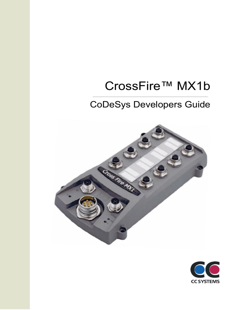
CrossFire™ MX1b CoDeSys Developers Guide CrossFire™ MX1b - CoDeSys Developers Guide Table of Contents Introduction .............................................................................................................................................................. 3 Purpose .............................................................................................................................................................. 3 References ......................................................................................................................................................... 3 History................................................................................................................................................................. 3 CoDeSys Development ........................................................................................................................................... 4 Background......................................................................................................................................................... 4 Installation........................................................................................................................................................... 4 Creating a new project in CoDeSys .................................................................................................................... 5 Accessing the I/O on your CrossFire MX1b ........................................................................................................ 5 Accessing the EEProm ....................................................................................................................................... 8 Accessing the CAN bus ...................................................................................................................................... 8 Programming Cable ............................................................................................................................................ 9 Writing an application in CoDeSys ...................................................................................................................... 9 Connecting to the target...................................................................................................................................... 9 Creating a boot project........................................................................................................................................ 9 PDO Communication .......................................................................................................................................... 9 Technical Support.................................................................................................................................................. 10 Trade Mark, etc ..................................................................................................................................................... 10 2 CrossFire™ MX1b - CoDeSys Developers Guide Introduction Purpose This document describes how the CrossFire™ MX1b with integrated programmable CoDeSys SoftPLC controller should be used. References CAN in Automation - CANopen standard: http://www.can-cia.org CE Marking: http://ec.europa.eu/ International Standards Organization: http://www.iso.org/ International Electrotechnical Commission http://www.iec.ch/ 3S - Smart Software Solutions GmbH – CoDeSys: http://www.3s-software.com History Rev 1.0 Date 2008-09-01 3 CrossFire™ MX1b - CoDeSys Developers Guide CoDeSys Development The following description assumes knowledge of CoDeSys. Background The CoDeSys runtime for CrossFire MX1b is a piece of software running on an Infineon C167 processor. It contains all necessary device drivers and software for communicating with the CoDeSys development editor. The runtime communicates with CoDeSys development editor by using RS232. Installation The runtime is preinstalled at the CrossFire MX1b when delivered. In order to start using the runtime with CoDeSys it is necessary to install a “target” for MX1b in CoDeSys. This is done with the program „Install Target‟ which is installed automatically when CoDeSys is installed. Follow these instructions: 1. Install CoDeSys. It can be downloaded from 3S web site. It can also be sent to you from CC Systems at request. The target is delivered in form of a zip-file, so first of all unzip the folder to a temporary location. 2. Start the program Install Target. It is found in the start menu of Windows at Start>Program->3S Software->CoDeSys V2.3->Install Target 3. In Install Target, choose ”Open”. Choose the target folder for CrossFire MX1b that has been delivered to you. 4. Choose the *.tnf file and open it. 5. The screen should look like this: 4 CrossFire™ MX1b - CoDeSys Developers Guide 1. You can change the installation folder, where all files will be put on your computer. This is done with the button “Installation directory”. However, it is recommended that you don‟t change the default settings. 2. Click Install. 3. Your target for CrossFire MX1 is now installed. Creating a new project in CoDeSys Start CoDeSys. In the first dialog that is shown you can choose your target. If you have followed the instruction for installing your target you should now be able to choose the CrossFire MX1b target. Normally you don‟t have to change any of the target settings for CrossFire MX1b. Just click OK after choosing CrossFire MX1b as your target. Accessing the I/O on your CrossFire MX1b The I/O on CrossFire MX1b can be found under PLC Configuration on the Resources tab in CoDeSys. It should look like this: 5 CrossFire™ MX1b - CoDeSys Developers Guide Under the I/O tree structure it is possible to access all I/O through variables. The variables are global and can thereby be accessed in all your code modules. It is also possible to change the names of the variables by clicking on them and writing a new name. For example, below, Port 1 which is a PWM output has been given the name MotorSpeed: The recommended way to access I/O however is by assigning I/O-addresses to global variables in your variable declaration list, e.g. like this: VAR_GLOBAL MotorSpeed AT %QW0:WORD; END_VAR This way the variable declaration is separated from the PLC Configuration. If the target installation is updated and variables are declared in PLC Configuration, the declarations will be lost. 6 CrossFire™ MX1b - CoDeSys Developers Guide Below all the accessible I/Os and configurations are described: Analog outputs (PWM) Port 1 – 8 on CrossFire MX1b are pwm outputs. The value range to set these outputs are 0 – 1023. Port 13 – 16 can be configured as pwm outputs by setting the corresponding Port configuration to the value 1. By default, Port 13 – 16 are configured as analog inputs. More info about port configuration is found under the chapter “Port configuration”. If ports 13 – 16 are not configured as analog outputs, the value of the analog output variables will be ignored. Note that the configuration of port 13 – 16 is individually done. It is possible to have some of the ports configured as analog inputs and others as analog outputs. Analog inputs Port 9 – 20 are by default configured as analog inputs. The value that can be read from the I/O variables is in the range 0 – 1023. Port 13 – 16 can also be configured as other kinds of I/O. Port 9 – 16 have the ability to have to different voltage measurement ranges; either 5 or 32 Volts. By default the range 0 – 5 volt is activated. If configured as 5 volt range, the value 1023 on the I/O variables means 5 volts. For 32 volt range the value 1023 means 32 volts. See more info about voltage ranges in the chapter Analog Input Voltage range. If any of the ports 13 – 16 are not configured as analog input, the corresponding I/O variable should be ignored. LEDS The LEDs on the CrossFire MX1b can be controlled with the I/O variables under LEDS. True means that the LED is on and FALSE means off. Port configuration of Port 13 – 16 With these variables it is possible to configure port 13 – 16. The possible values for every port are listed in the comments for the variables. If a port is configured as an analog output, the variable under Analog outputs should be used to control the port. If a port is configured as analog input, the variable under Analog Input should be used for reading the AD value of the port. If a port is configured as Frequency input, the pulse counter value of the port can be read in the variables under Frequency. It is possible to use port 13 and 14 to work together as an encoder input. Both port 13 and 14 have to be configured as encoder input in that case. The behavior is not defined if only one port is configured as encoder input. When ports 13 and 14 is used as encoder input, the frequency variable for port 13 contains the pulse counter, which counts both upwards and downwards depending of the direction of the encoder shaft. Analog input voltage range for port 9 – 16 The analog inputs of ports 9 – 16 have adjustable voltage ranges; either 5 volts or 32 volts. If the corresponding variable is set to TRUE the 32 volt range is activated. If FALSE the 5 volt range is activated (default). PWM Ripple frequency By setting a value to the pwm ripple frequency variable it is possible to set the pwm ripple frequency for pwm port 1 – 8. The value range is 0 – 1000 Hz. Output status for port 1 - 8 For each output port 1 – 8 there is a byte that tells the status of the output port. Value 0 means that the output is Ok. Value 1 means that the output has open load. Value 2 means that a too high current is flowing though the output. Value 3 means that a short-to-ground condition was detected. 7 CrossFire™ MX1b - CoDeSys Developers Guide Open load detection is only done the first 10 ms after power-on. If an open load condition occurs after the first 10 ms it will not be detected. If an over-current or short-to-ground condition is detected, the output of that port is turned off in order to protect the hardware. It is necessary to turn off power to the unit to recover and start using the output again. Frequency/Encoder pulse counters for Port 13 and 14 These variables are used if port 13 or 14 is configured as frequency inputs or encoder inputs. If any of the ports are configured as frequency inputs, the variables counts up for every pulse that reaches the port pins. The counter value can of course be converted to a frequency value by writing the proper software in CoDeSys user application. If both port 13 and 14 are configured as encoder inputs, the port pins work together as a encoder input. Only the pulse counter for port 13 should then be read. The counter will count either upwards or downwards depending on the direction of the encoder shaft. Note. The behavior of the software is not defined if only one of port 13 and 14 is configured. It is therefore important that both ports are configured as encoder inputs. Accessing the EEProm In order to access the eeprom of the unit, the library EEPROM_DRV.lib has to be loaded. This is done under the Resource Tab in CoDeSys. Choose Library manager. Chose Insert>Additional Library from the menu in CoDeSys. Now, a dialog should appear with all the libraries that were installed with the target. Choose the EEPROM_DRV.lib library. Now the library is loaded and the functions EEProm_Init, EEProm_Write, EEProm_Read and EEProm_GetSize are ready to be used. The explanation of parameter and return values of the functions can be found in the library manager. Note. If power to the unit is lost during a write operation to the EEprom, the content of the EEprom may be corrupted. However, it is possible to write mechanisms in the CoDeSys software to recover from corrupted eeprom. This can for example be done by always writing to two different areas. At startup the areas can be compared, and thereby corruption of the eeprom can be detected and corrected. Accessing the CAN bus The CAN bus is accessed by using the library 3S_CanDrv.lib. This library is described in the CoDeSys documentation. Normally the user does not access the CAN bus directly with this library. Instead a CANopen master is added in the PLC configuration. This is also described in the CoDeSys documentation. 8 CrossFire™ MX1b - CoDeSys Developers Guide Programming Cable The CoDeSys application is downloaded via RS232 and the serial cable should be attached to the CrossFire MX1b like this: MX1b Power Supply connector 5 (TxD) 6 (RxD) 4 (GND) D-sub female 2 (RxD) 3 (TxD) 5 (GND) Writing an application in CoDeSys How to write an application in CoDeSys is not described in this document. The reader should instead use the manuals that were installed together with CoDeSys. 3S is responsible for the manuals of CoDeSys. Connecting to the target When you have your CoDeSys project ready you need to download it to your hardware. First you have to set your communication parameters. This is done in the menu Online>Communication parameters in CoDeSys. In the dialog, click New and the choose Serial (RS232). Click Ok. Now you are ready to download your project. Choose Online->Login. CoDeSys will ask you if you want to download your application. Click Yes. Now your application should start downloading. When it is downloaded you can start and debug your program. For more information, consult your CoDeSys documentation. Creating a boot project When you download your project to your hardware it is only downloaded to the RAM memory. If you turn off power to your hardware the project will be lost, and you have to download it again. In order to save the project in the flash memory of the hardware you have to create a boot project. When you‟re logged in to the hardware choose Online->Create boot project. The project will now be copied from the RAM memory to the flash memory. The next time the unit starts; it will automatically load the program from the flash memory to the RAM memory and start executing the code. PDO Communication In case the unit is configured as a CanDevice a filter has to be set in order to be able to receive PDO‟s. The filter is set with the function Can_SetFilter(), which is located in the 3S_CanDrv.lib library. FUNCTION Can_SetFilter : BOOL VAR_INPUT 9 CrossFire™ MX1b - CoDeSys Developers Guide nCanDRVNr : INT; dwMask : DWORD; dwAczept : DWORD; END_VAR Parameters nCanDRVNr should be 0 because this is the first CanDevice (and there can be only one). dwMask should be 0. dwAczept Determines the range of COB-ID‟s of PDO‟s that‟s possible to receive. The 16 LSB determines the lowest COB-ID to let trough. The 16 MSB determines the highest possible COB-ID. For example to let PDOs with COB id between 0x202 and 0x502 trough, the function call should look like this: Can_SetFilter(0, 0, 16#5020202); This function has to be called every program loop in the task that handles the CAN communication. Technical Support Contact your reseller or supplier for help with possible problems with your CrossFire™ MX1b. In order to get the best help, you should have access to your CrossFire™ MX1b and be prepared with the following information before you contact support. Part number and serial number of the unit, which you find on the brand label Date of purchase, which is found on the invoice The conditions and circumstances under which the problem arises LED indicator colours and blink patterns. EMCY object error codes (if possible) Description of external equipment which is connected to the CrossFire™ MX1b Trade Mark, etc © 2006 CC Systems AB All trademarks sighted in this document are the property of their respective owners. CrossFire™ MX1b is a trademark which is the property of CC Systems AB. CiA is a registered trademark which is the property of CAN in Automation. CoDeSys is a product name of 3S Smart Software Solutions GmbH. CC Systems AB is not responsible for editing errors, technical errors or for material which has been omitted in this document. CC Systems is not responsible for unintentional damage or for damage which occurs as a result of supplying, handling or using of this material. The information in this handbook is supplied without any guarantees and can change without prior notification. 10


