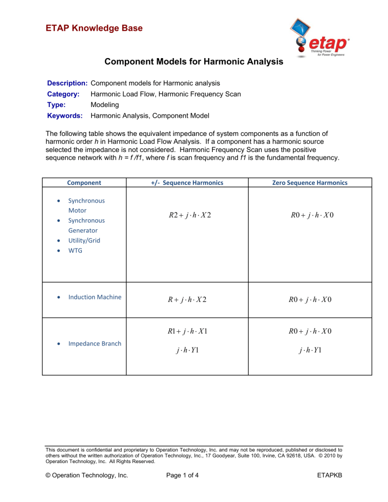
ETAP Knowledge Base Component Models for Harmonic Analysis Description: Component models for Harmonic analysis Category: Harmonic Load Flow, Harmonic Frequency Scan Type: Modeling Keywords: Harmonic Analysis, Component Model The following table shows the equivalent impedance of system components as a function of harmonic order h in Harmonic Load Flow Analysis. If a component has a harmonic source selected the impedance is not considered. Harmonic Frequency Scan uses the positive sequence network with h = f /f1, where f is scan frequency and f1 is the fundamental frequency. Component Synchronous Motor Synchronous Generator Utility/Grid WTG Induction Machine Impedance Branch +/‐ Sequence Harmonics Zero Sequence Harmonics R2 j h X 2 R0 j h X 0 R jh X 2 R0 j h X 0 R1 j h X 1 R0 j h X 0 j h Y1 j h Y1 This document is confidential and proprietary to Operation Technology, Inc. and may not be reproduced, published or disclosed to others without the written authorization of Operation Technology, Inc., 17 Goodyear, Suite 100, Irvine, CA 92618, USA. © 2010 by Operation Technology, Inc. All Rights Reserved. © Operation Technology, Inc. Page 1 of 4 ETAPKB ETAP Knowledge Base Component Models for Harmonic Analysis Component +/‐ Sequence Harmonics Zero Sequence Harmonics 1 1 1 R eq j h X eq Static Load Lumped Load (all load types) MOV V2 P V2 Q Req X eq Same as +/‐ Seq. (P and Q are the fundamental real and reactive power into the load. V is the fundamental load terminal voltage.) Transformer Reactor R1 (0.8 0.2 h 2 ) j h X 1 R0 (0.8 0.2 h 2 ) j h X 0 Pos. Sequence R1 [1 0.2 log(h)] j Transmission Line (Short) Cable (Short) h X1 1 0.1 log(h) j h Y1 R0 [1 0.2 log(h)] j Neg. Sequence R 2 [1 0.2 log(h)] j h X0 1 0.1 log(h) h X 2 1 0.1 log(h) j h Y 2 This document is confidential and proprietary to Operation Technology, Inc. and may not be reproduced, published or disclosed to others without the written authorization of Operation Technology, Inc., 17 Goodyear, Suite 100, Irvine, CA 92618, USA. © 2010 by Operation Technology, Inc. All Rights Reserved. © Operation Technology, Inc. Page 2 of 4 ETAPKB ETAP Knowledge Base Component Models for Harmonic Analysis Component +/‐ Sequence Harmonics Zero Sequence Harmonics Pos. Sequence z R1 j h X 1 y j h Y1 z R0 j h X 0 y j h Y 0 Neg. Sequence Transmission Line (Long) Cable (Long) z R2 j h X 2 y j h Y 2 Z line / cab z y Yline / cab 2 z sinh y z y UPS VFD Charger Inverter PV Array HVDC Link SVC See Remark 1 See Remark 1 Capacitor j Xc h V2 Xc Q Same as +/‐ Seq. This document is confidential and proprietary to Operation Technology, Inc. and may not be reproduced, published or disclosed to others without the written authorization of Operation Technology, Inc., 17 Goodyear, Suite 100, Irvine, CA 92618, USA. © 2010 by Operation Technology, Inc. All Rights Reserved. © Operation Technology, Inc. Page 3 of 4 y 1 tanh z y z 2 y 1 tanh z y z 2 Yline / cab 2 z sinh y Z line / cab ETAPKB ETAP Knowledge Base Component Models for Harmonic Analysis Component +/‐ Sequence Harmonics Zero Sequence Harmonics j Xc h Capacitors: ‐ Inductors: j h Xl Same as +/‐ Seq. Harmonic Filter Resistors: R (The equivalent impedance depends on the topology of the filter selection) Remarks: 1. In ETAP 11, all power electronic type devices are to be modeled as a harmonic source or else they will be seen as infinite impedance. 2. Numerals 1, 2, and 3 denote positive, negative, and zero sequence respectively This document is confidential and proprietary to Operation Technology, Inc. and may not be reproduced, published or disclosed to others without the written authorization of Operation Technology, Inc., 17 Goodyear, Suite 100, Irvine, CA 92618, USA. © 2010 by Operation Technology, Inc. All Rights Reserved. © Operation Technology, Inc. Page 4 of 4 ETAPKB


