Virtual Channel-Less Five Port Network-on-Chip Router Design
advertisement

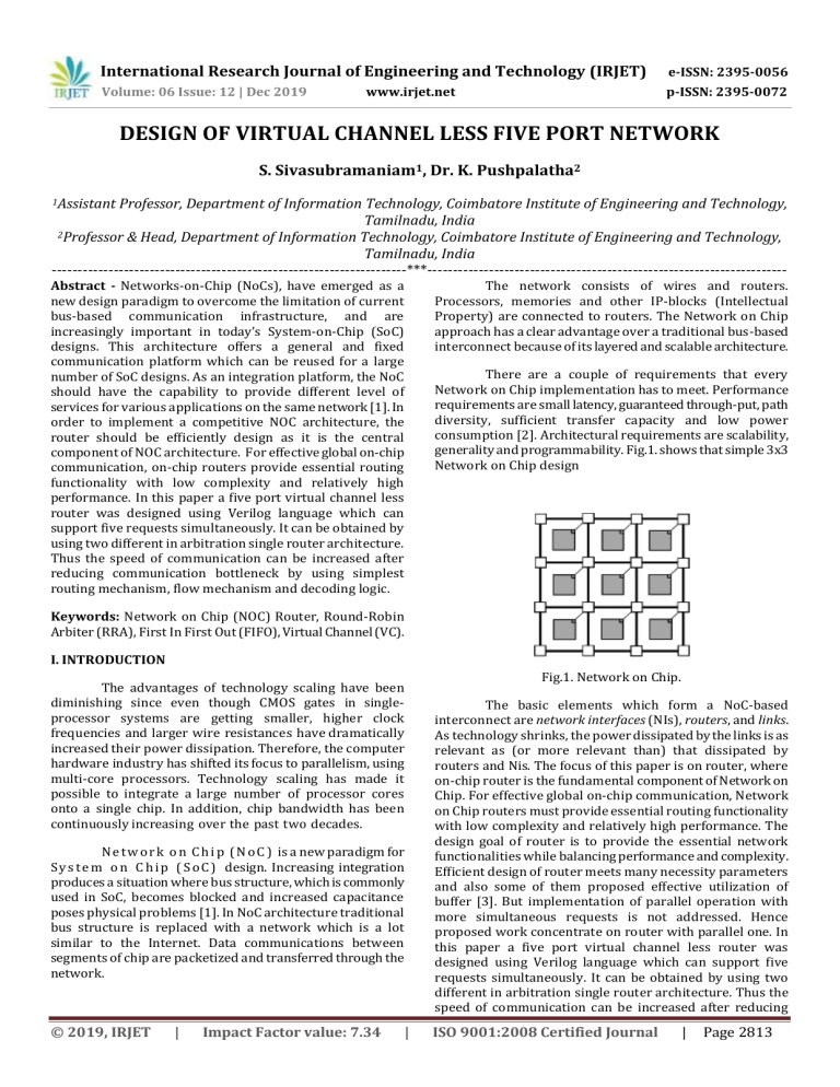
International Research Journal of Engineering and Technology (IRJET) e-ISSN: 2395-0056 Volume: 06 Issue: 12 | Dec 2019 p-ISSN: 2395-0072 www.irjet.net DESIGN OF VIRTUAL CHANNEL LESS FIVE PORT NETWORK S. Sivasubramaniam1, Dr. K. Pushpalatha2 1Assistant Professor, Department of Information Technology, Coimbatore Institute of Engineering and Technology, Tamilnadu, India 2Professor & Head, Department of Information Technology, Coimbatore Institute of Engineering and Technology, Tamilnadu, India ---------------------------------------------------------------------***---------------------------------------------------------------------Abstract - Networks-on-Chip (NoCs), have emerged as a new design paradigm to overcome the limitation of current bus-based communication infrastructure, and are increasingly important in today’s System-on-Chip (SoC) designs. This architecture offers a general and fixed communication platform which can be reused for a large number of SoC designs. As an integration platform, the NoC should have the capability to provide different level of services for various applications on the same network [1]. In order to implement a competitive NOC architecture, the router should be efficiently design as it is the central component of NOC architecture. For effective global on-chip communication, on-chip routers provide essential routing functionality with low complexity and relatively high performance. In this paper a five port virtual channel less router was designed using Verilog language which can support five requests simultaneously. It can be obtained by using two different in arbitration single router architecture. Thus the speed of communication can be increased after reducing communication bottleneck by using simplest routing mechanism, flow mechanism and decoding logic. The network consists of wires and routers. Processors, memories and other IP-blocks (Intellectual Property) are connected to routers. The Network on Chip approach has a clear advantage over a traditional bus-based interconnect because of its layered and scalable architecture. There are a couple of requirements that every Network on Chip implementation has to meet. Performance requirements are small latency, guaranteed through-put, path diversity, sufficient transfer capacity and low power consumption [2]. Architectural requirements are scalability, generality and programmability. Fig.1. shows that simple 3x3 Network on Chip design Keywords: Network on Chip (NOC) Router, Round-Robin Arbiter (RRA), First In First Out (FIFO), Virtual Channel (VC). I. INTRODUCTION The advantages of technology scaling have been diminishing since even though CMOS gates in singleprocessor systems are getting smaller, higher clock frequencies and larger wire resistances have dramatically increased their power dissipation. Therefore, the computer hardware industry has shifted its focus to parallelism, using multi-core processors. Technology scaling has made it possible to integrate a large number of processor cores onto a single chip. In addition, chip bandwidth has been continuously increasing over the past two decades. N e t w o r k o n C h i p ( N o C ) is a new paradigm for S y s t e m o n C h i p ( S o C ) design. Increasing integration produces a situation where bus structure, which is commonly used in SoC, becomes blocked and increased capacitance poses physical problems [1]. In NoC architecture traditional bus structure is replaced with a network which is a lot similar to the Internet. Data communications between segments of chip are packetized and transferred through the network. © 2019, IRJET | Impact Factor value: 7.34 | Fig.1. Network on Chip. The basic elements which form a NoC-based interconnect are network interfaces (NIs), routers, and links. As technology shrinks, the power dissipated by the links is as relevant as (or more relevant than) that dissipated by routers and Nis. The focus of this paper is on router, where on-chip router is the fundamental component of Network on Chip. For effective global on-chip communication, Network on Chip routers must provide essential routing functionality with low complexity and relatively high performance. The design goal of router is to provide the essential network functionalities while balancing performance and complexity. Efficient design of router meets many necessity parameters and also some of them proposed effective utilization of buffer [3]. But implementation of parallel operation with more simultaneous requests is not addressed. Hence proposed work concentrate on router with parallel one. In this paper a five port virtual channel less router was designed using Verilog language which can support five requests simultaneously. It can be obtained by using two different in arbitration single router architecture. Thus the speed of communication can be increased after reducing ISO 9001:2008 Certified Journal | Page 2813 International Research Journal of Engineering and Technology (IRJET) e-ISSN: 2395-0056 Volume: 06 Issue: 12 | Dec 2019 p-ISSN: 2395-0072 www.irjet.net communication bottleneck by using simplest routing mechanism, flow mechanism and decoding logic. Therefore, for a flit size of w, the first 8-bits are used to indicate the flit type and the address II. ROTER MICROARCHITECTURE In this section we will discuss the details of the proposed router microarchitecture used for NOC. I have omitted the use of Virtual Channels (VCs) instead of VCs would just add another layer of arbitration at the input ports of the router [5]. In this block diagram, the letter p corresponds to the number of ports (in this case p = 5), and the letter w refers to the port width which is also the flit size. The first stage of the router consists of an input buffer to store the incoming flits that make up the messages. The header bits of each flit are supplied to the State module which determines the type of the flit (head flit, body flit, or tail flit), and the output destination of the message. Once the output port has been determined using a lookup table, a request signal (req) is sent to the Round Robin Arbiter. After arbitration, the arbiter sends a grant signal to the priority encoder, which Fig.3. Flit partition of the destination core (represented as in[7:0] in Fig.2). The partition of the flit is shown in the diagram of Fig.3. In Table 1, we have shown the different flit identifiers we have used to code the flit types. 2-bits are used for the flit identifier and 6-bits for the destination address of the flit. We will now discuss the implementation of the various router components in Figure 5.1 in more detail. In Table 1, we have shown the different flit identifiers we have used to code the flit types. We will now discuss the implementation of the various router components in Fig.2. in more detail. Table 1 Flit Identifier types and codes Head Flit Identifier 11 Body 10 Tail 01 Not-Used 00 Flit Type A. State Module The State module has 4 main functions. First, it evaluates the flit identifier to find out whether the incoming flit is a head, body, or tail flit. Next, it uses the 6-bit destination address in the flit to determine which router output port the flit/message should be sent to using a lookup table. The output port address for each flit/message is stored in the State module. Then the State module sends a request (req) signal to the arbiter to allow the flits to traverse the crossbar. And finally, the State module reserves the output port so that other input ports cannot use the same output port until it is released. Fig. 2. Proposed Router microarchitecture connects the corresponding input and output ports of the crossbar so that the flit can traverse through the crossbar and reach its destination. At the same time, the arbiter also sends a credit signal to the corresponding input port to release one flit in the buffer so that a new flit can take its place. The letter p corresponds to the number of ports and w represents the port width. In this diagram p = 5. We need 2-bits to represent the incoming flit identifier: head, body, or tail. © 2019, IRJET | Impact Factor value: 7.34 | B. Round Robin Arbiter We chose a simple Round Robin arbiter for our router [5]. A Round Robin arbiter was chosen since it is simple to implement and because it exhibits strong fairness. The Round Robin arbiter operates by assigning a low ISO 9001:2008 Certified Journal | Page 2814 International Research Journal of Engineering and Technology (IRJET) e-ISSN: 2395-0056 Volume: 06 Issue: 12 | Dec 2019 p-ISSN: 2395-0072 www.irjet.net priority to a request that has just been granted access to the crossbar. All other pending requests will be serviced before the priority rotates around in a circular fashion [5]. Once a request is granted access to the crossbar, the arbiter sends a grant signal to the encoder which is described next The multiplexer crossbar operates in a manner completely analogous to the matrix crossbar, in the sense that it uses the same select line (sel[p-1:0]) vectors from the Encoder and connects the corresponding input to the appropriate output line as determined by the State module. C. Buffering In this case a multiplexer is used for switching. Each input port connects to a multiplexer at the output ports, and the select line is used to choose the appropriate input port for each output. The input and output registers shown in Fig.4. are the same registers that were shown in the router microarchitecture diagram of Fig.2. Buffering is required in most on-chip routers to provide temporary storage of packets that are in transit. Buffering is implemented mostly with FIFO memory. Buffer size and the buffering scheme are the two main considerations. In FIFO there are two chip select they are write chip select (wr_cs) read chip select (rd_cs) which is used to select the appropriate chip for read and write operation. Empty and full are the two variables stores number of read and write operation on the FIFO buffers. These variables are used to know whether the FIFO is empty or full. When enable signal read (rd_en) is high, control logic first check fifo empty signal. If it is high operation is terminated and if it is low packet is read from the memory and cr is incremented by one. When write enable signal (wr_en) is high, control logic first check fifo full signal. If fifo full is high, it means memory is full and no more packets are added in it and operation is terminated. But if it is low, packet is write into the Memory [9]. E. Encoder The Encoder accepts the grant signal from the Round Robin arbiter, and using the Output Port Address (S[0:2] in Fig.4.) stored in the State module, the Encoder generates a p-bit select line signal for each output port, where p is the number of input ports. The select signal is issued such that only one of the p-bits is high while the remaining bits are low. This ensures that at any point in time, only one input port can drive an output port at the crossbar. III. SIMULATIONS & RESULTS A. Round Robin: Packets with the same priority and destined for the same output port are scheduled with a round-robin arbiter. Round Arbiter can be designed in Verilog & RTL schematic of Round Robin shown in Fig.5. Fig.5. RTL schematic of Round Robin Table 2. Round Robin Function Fig.4. A 5x5 Multiplexer Crossbar. S.No 1. 2. 3. 4. 5. D. Multiplexer Crossbar Crossbars can come in different flavors, and another type of crossbar we will be looking into is the multiplexer crossbar (or centralized multiplexer) shown in Fig.4. Req [4:0] 00001 00010 00011 01100 10000 Grant [4:0] 00001 00010 00001, 00010 00100 01000 10000 Credit [4:0] 11110 11101 11110, 11101 11011 10111 01111 Based on request signal, grant signal will be generate. In the below Fig.6. input request 00011 is given and grant signal obtained is 00001, 00010, 00000. In this © 2019, IRJET | Impact Factor value: 7.34 | ISO 9001:2008 Certified Journal | Page 2815 International Research Journal of Engineering and Technology (IRJET) e-ISSN: 2395-0056 Volume: 06 Issue: 12 | Dec 2019 p-ISSN: 2395-0072 www.irjet.net there are ones in request signal based on that, design generated two grant signals Fig.9. RTL schematic of Crossbar Fig.6. Output Waveform for Round Robin B. Encoder: In proposed design architecture encoder is used to generate selection lines for cross bar. It generates four selection lines based on the grant input and state input. Encoder can be designed in Verilog & RTL schematic of Encoder shown in Fig.7. Fig.10. Output Waveform for Crossbar IV. CONCLUSION In the current silicon era, NoC is not power and area efficient although it has higher throughput. Enhancement in the utilization of idle resources instead of inserting new ones can make the NoC an ideal solution for current applications. One such problem is the design of the router micro architecture to cope with ever increasing bandwidth requirements, while minimizing the area overhead and power consumption. The proposed NOC virtual channel less micro router architecture are more area and power efficient compared to virtual channel routers. Proposed NOC virtual channel less micro router architecture are designed using Verilog hardware description language, synthesis with the help of Xilinx ISE 14.1 software and design can be simulated using Isim simulator. Fig.7. RTL schematic of Encoder REFERNCES [1] Yuho Jin, Member, Eun Jung Kim and Timothy Mark Pinkston, Yuho Jin: Communication-Aware GloballyCoordinated On-Chip Networks IEEE Transactions On Parallel and Distributed Systems, vol. 23, no. 2, February 2018 [2] Radu Marculescu, Umit Y. Ogras, Li-Shiuan Peh, Natalie Enright Jerger, and Yatin Hoskote Outstanding Research Problems in NoC Design: System, Microarchitecture, and Circuit Perspectives, IEEE Transactions On ComputerAided Design of Integrated Circuits and Systems, vol. 28, no. 1, January 2016 Fig.8. Output Waveform for Encoder C. MUX_5X5 _XBAR: In proposed design architecture crossbar is used to connect input to output, it can be connected based on the four selection lines. [3] © 2019, IRJET | Impact Factor value: 7.34 | Faizal Arya Samman, Thomas Hollstein and Manfred Glesner,: Adaptive and Deadlock-Free Tree-Based Multicast routing for Networks-on-Chip, IEEE ISO 9001:2008 Certified Journal | Page 2816 International Research Journal of Engineering and Technology (IRJET) e-ISSN: 2395-0056 Volume: 06 Issue: 12 | Dec 2019 p-ISSN: 2395-0072 www.irjet.net Transactions On Very Large Scale Integration (VLSI) systems, vol. 18, no. 7, July 2015 [4] T.A. Bartic, J.-Y. Mignolet, V. Nollet, T. Marescaux, D. Verkest, S. Vernalde, R. Lauwereins: Topology adaptive network-on-chip design and implementation. IEE Proceedings – Computers and Digital Techniques, 8 July 2005, Volume 152, Issue 4, pages: 467–472. [5] W.J. Dally, B. Towles: Principles and Practices of Interconnection Net-works. Morgan Kaufmann, 2014. [6] W.J. Dally, B. Towles: Route Packets, Not Wires: OnChip Interconnection Networks. Proceedings, Design Automation Conference 2001, pages: 684– 689. [7] G. De Micheli, L. Benini: Networks on Chips. Morgan Kaufmann, 2006. [8] M. Dehyadgari, M. Nickray, A. Afzali-kusha, Z. Navabi: Evaluation of Pseudo Adaptive XYRouting Using an Object Oriented Model for NOC. The 17th International Conference on Microelectronics, 13–15 December 2005. [9] J. Dielissen, A. Radulescu, K. Goossens, E. Rijpkema: Concepts and Implementation of the Philips Network-onChip. IP-Based SOC Design, Grenoble, France, Nov 2003. [10] U. Feige, P. Raghavan: Exact Analysis of Hot-Potato Routing. Foundations of Computer Science, 24–27 October 1992, pages: 553–562. © 2019, IRJET | Impact Factor value: 7.34 | ISO 9001:2008 Certified Journal | Page 2817


