Sierpinski Fractal Antenna Design & Simulation Analysis
advertisement

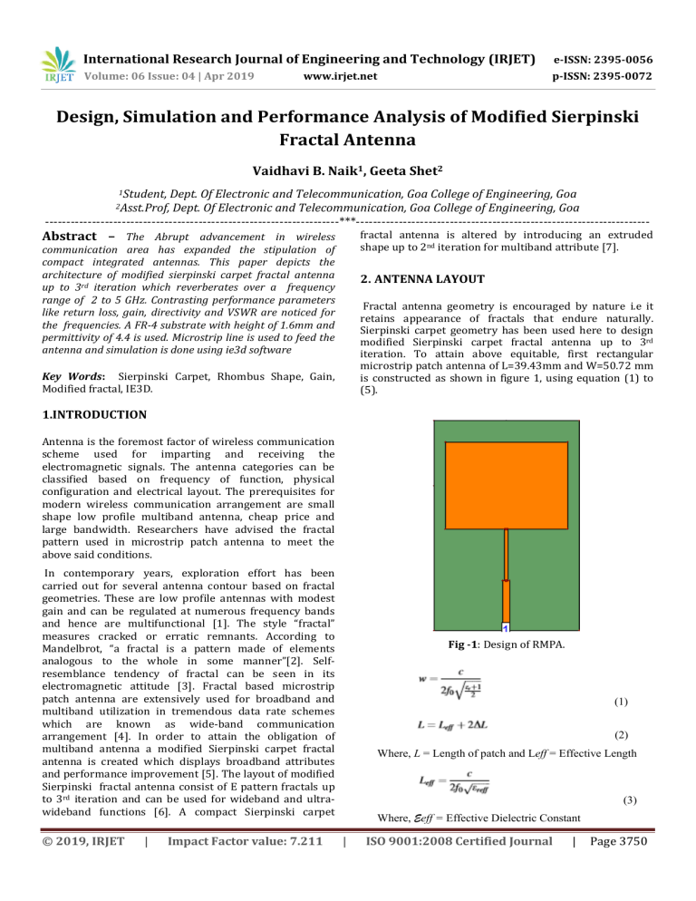
International Research Journal of Engineering and Technology (IRJET) e-ISSN: 2395-0056 Volume: 06 Issue: 04 | Apr 2019 p-ISSN: 2395-0072 www.irjet.net Design, Simulation and Performance Analysis of Modified Sierpinski Fractal Antenna Vaidhavi B. Naik1, Geeta Shet2 1Student, Dept. Of Electronic and Telecommunication, Goa College of Engineering, Goa Dept. Of Electronic and Telecommunication, Goa College of Engineering, Goa ---------------------------------------------------------------------***--------------------------------------------------------------------2Asst.Prof, Abstract – The Abrupt advancement in wireless fractal antenna is altered by introducing an extruded shape up to 2nd iteration for multiband attribute [7]. communication area has expanded the stipulation of compact integrated antennas. This paper depicts the architecture of modified sierpinski carpet fractal antenna up to 3rd iteration which reverberates over a frequency range of 2 to 5 GHz. Contrasting performance parameters like return loss, gain, directivity and VSWR are noticed for the frequencies. A FR-4 substrate with height of 1.6mm and permittivity of 4.4 is used. Microstrip line is used to feed the antenna and simulation is done using ie3d software 2. ANTENNA LAYOUT Fractal antenna geometry is encouraged by nature i.e it retains appearance of fractals that endure naturally. Sierpinski carpet geometry has been used here to design modified Sierpinski carpet fractal antenna up to 3rd iteration. To attain above equitable, first rectangular microstrip patch antenna of L=39.43mm and W=50.72 mm is constructed as shown in figure 1, using equation (1) to (5). Key Words: Sierpinski Carpet, Rhombus Shape, Gain, Modified fractal, IE3D. 1.INTRODUCTION Antenna is the foremost factor of wireless communication scheme used for imparting and receiving the electromagnetic signals. The antenna categories can be classified based on frequency of function, physical configuration and electrical layout. The prerequisites for modern wireless communication arrangement are small shape low profile multiband antenna, cheap price and large bandwidth. Researchers have advised the fractal pattern used in microstrip patch antenna to meet the above said conditions. In contemporary years, exploration effort has been carried out for several antenna contour based on fractal geometries. These are low profile antennas with modest gain and can be regulated at numerous frequency bands and hence are multifunctional [1]. The style “fractal” measures cracked or erratic remnants. According to Mandelbrot, “a fractal is a pattern made of elements analogous to the whole in some manner”[2]. Selfresemblance tendency of fractal can be seen in its electromagnetic attitude [3]. Fractal based microstrip patch antenna are extensively used for broadband and multiband utilization in tremendous data rate schemes which are known as wide-band communication arrangement [4]. In order to attain the obligation of multiband antenna a modified Sierpinski carpet fractal antenna is created which displays broadband attributes and performance improvement [5]. The layout of modified Sierpinski fractal antenna consist of E pattern fractals up to 3rd iteration and can be used for wideband and ultrawideband functions [6]. A compact Sierpinski carpet © 2019, IRJET | Impact Factor value: 7.211 Fig -1: Design of RMPA. (1) (2) Where, L = Length of patch and Leff = Effective Length (3) Where, Eeff = Effective Dielectric Constant | ISO 9001:2008 Certified Journal | Page 3750 International Research Journal of Engineering and Technology (IRJET) e-ISSN: 2395-0056 Volume: 06 Issue: 04 | Apr 2019 p-ISSN: 2395-0072 www.irjet.net (4) (5) Next the rectangular patch antenna is cleft into 9 proportionate sub rectangles and center most sub rectangle has been modified to (1) rhombus shaped Sierpinski carpet and (2) rhombus inscribed in a rectangle Sierpinski carpet. Analogous steps have been carried out for iteration 2 and 3 for rhombus shaped Sierpinski carpet and rhombus inscribed in a rectangle Sierpinski carpet as shown in figure 2 and 3 respectively. Fig 3-: Design of rhombus inscribed in rectangle SCFA 3. SIMULATION RESULTS The RMPA antenna graph in Fig.4 gives a return loss of -12.042 dB at 1.8 GHz. The graph seen in Fig.5 gives a gain of 0.62 dBi at 1.8 GHz. The rhombus shaped SCFA and rhombus inscribed in a rectangle SCFA resonate over two frequencies. The graphs in Fig.6 and Fig.8 show the return loss of rhombus shaped SCFA and rhombus inscribed in a rectangle SCFA respectively. The graphs seen in Fig.7 and Fig.9 show the gain of rhombus shaped SCFA and rhombus inscribed in a rectangle SCFA respectively. The results of each antenna and their performance are outlined in Table 1. Fig 2-: Design of rhombus shaped SCFA Fig 4-: S11 of RMPA © 2019, IRJET | Impact Factor value: 7.211 | ISO 9001:2008 Certified Journal | Page 3751 International Research Journal of Engineering and Technology (IRJET) e-ISSN: 2395-0056 Volume: 06 Issue: 04 | Apr 2019 p-ISSN: 2395-0072 www.irjet.net Fig 8-: S11 of rhombus inscribed in rectangle SCFA Fig 5-: Gain of RMPA Fig 6-: S11 of rhombus shaped SCFA Fig 9-: Gain of rhombus inscribed in rectangle SCFA Fig 7-: Gain of rhombus shaped SCFA © 2019, IRJET | Impact Factor value: 7.211 | ISO 9001:2008 Certified Journal | Page 3752 International Research Journal of Engineering and Technology (IRJET) e-ISSN: 2395-0056 Volume: 06 Issue: 04 | Apr 2019 p-ISSN: 2395-0072 www.irjet.net Research in Electronics and Communication Engineering (IJARECE),Volume 4, Issue 8, August 2015 [7] Sejal Kundalia and Vivek Unadkat,”Modified Sierpinski Carpet Fractal Antenna For Wireless Communication”, National Conference on Emerging Trends in Computer, Electrical & Electronics (ETCEE-2015) and International Journal of Advance Engineering and Research Development (IJAERD). [8] Zealand IE3D software Inc. ver. 14.0. Table -1: Optimized parameters Paramet ers Antenna Rhombus shaped SCFA RMPA Rhombus inscribed in rectangle SCFA Resonant Frequency 1.8 GHz 2.4 GHz 4.6 GHz 2.4 GHz 4.8 GHz Return loss (in dB) -12.042 -25.4326 -18.3231 -27.7612 -18.548 Gain(in dBi) 0.62 4.22662 4.12625 4.18202 3.35355 VSWR 1.8 1.11526 1.27624 1.08533 1.26807 Directivity (in dBi) 6.22 4.28091 4.96988 4.2178 4.19826 4. CONCLUSIONS A rhombus shaped sierpinski carpet and rhombus inscribed in a rectangle sierpinski carpet fractal antenna at 1.8 GHz has been created up to 3rd iteration in this paper using IE3D software. It has been investigated for parameters such as return loss, VSWR, gain and directivity. It can be achieved from above simulation outcomes that rhombus shaped and rhombus inscribed in a rectangle can be used over a range of 2-5 GHz. REFERENCES [1] [2] [3] [4] [5] [6] Roopa. R, Jayadevat .S., Manassarkar & Dr. Y. S. Kumarswamy, “Design Of Sierpinski Carpet Sierpinski Fractal Antenna By Improving The Performance Parameters And Reducing The Antenna Size”, 2013 IEEE Conference on Information & Communication Technologies. Dipika S. Sagne, Rahul S. Batra & P.L. Zade,Design Of Modified Geometry Sierpinski Carpet Fractal Antenna Array For Wireless Communication”, 2013 3rd IEEE International Advance Computing Conference(IACC). D. H. Werner and S. Ganguly, “An Overview Of Fractal Antenna Engineering Research,” IEEE Antennas Propagation Mag., vol. 45, no. 1, Feb. 2003. Jagtar Singh Sivia and Sumeet Singh Bhatia, “Design of Fractal Based Microstrip Rectangular Patch Antenna for Multiband Applications”,2015 IEEE International Advance Computing Conference (IACC). T.Kalaimani,P.MaheswaraVenkateshR.Mohanamuralia nd T.Shanmuganantham,“A Modified Sierpinski Carpet FractalAntennaforWirelessApplications”,International conference on Communication and Signal Processing, April 3-5, 2013, India. Sukhveer Singh, Savina Bansal and Sukhjinder Singh3,”Design and Analysis of E-Shape Sierpinski Fractal Antenna”,International Journal of Advanced © 2019, IRJET | Impact Factor value: 7.211 | ISO 9001:2008 Certified Journal | Page 3753


