IRJET-Implementation of Lenz Law for the Application of Electromagnetic Disk Braking
advertisement

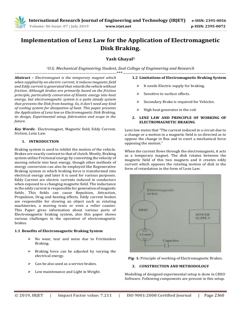
International Research Journal of Engineering and Technology (IRJET) e-ISSN: 2395-0056 Volume: 06 Issue: 07 | July 2019 p-ISSN: 2395-0072 www.irjet.net Implementation of Lenz Law for the Application of Electromagnetic Disk Braking. Yash Ghayal1 1U.G. Mechanical Engineering Student, Zeal College of Engineering and Research ---------------------------------------------------------------------***---------------------------------------------------------------------- Abstract – Electromagnet is the temporary magnet which when supplied by an electric current, it induces magnetic field and Eddy current is generated that retards the vehicle without friction. Although brakes are primarily based on the friction principle, particularly conversion of Kinetic energy into heat energy, but electromagnetic system is a quite steady system that prevents the Disk from heating. So, it don’t need any kind of cooling system for dissipation of heat. This paper presents the Application of Lenz law as Electromagnetic Disk Braking, its design, Experimental setup, fabrication and scope in the future. 1.2 Limitations of Electromagnetic Braking System Key Words: Electromagnet, Magnetic field, Eddy Current, friction, Lenz Law. Lenz law states that “The current induced in a circuit due to a change or a motion in a magnetic field is so directed as to oppose the change in flux and to exert a mechanical force opposing the motion.” It needs Electric supply for braking. Sensitive to surface effects. Secondary Brake is required for Vehicles. High heat generates in the coil. 2. LENZ LAW AND PRINCIPLE OF WORKING OF ELECTROMAGNETIC BRAKING 1. INTRODUCTION Braking system is used to inhibit the motion of the vehicle. Brakes are exactly contrast to that of clutch. Mostly, Braking system utilize Frictional energy by converting the velocity of moving vehicle into heat energy, though other methods of energy conversion can also be employed like Regenerative Braking system in which braking force is transformed into electrical energy and later it is used for various purposes. Eddy Current are electric currents induced in conductors when exposed to a changing magnetic field. The inductance in the eddy current is responsible for generation of magnetic fields. This fields can cause Repulsion, Attraction, Propulsion, Drag and heating effects. Eddy current brakes are responsible for slowing an object such as rotating machineries, a moving train or even a roller coaster. This Paper gives information about various parts of Electromagnetic braking system, also this paper shows various challenges in the operation of electromagnetic brakes. When the current flows through the electromagnets, it acts as a temporary magnet. The disk rotates between the magnetic field of this two magnets and it creates eddy current which opposes the rotating motion of disk in the form of retardation in the form of Lenz Law. 1.1 Benefits of Electromagnetic Braking System No wear, tear and noise due to Frictionless Braking. Braking force can be adjusted by varying the electrical energy. Can be also used as a service brakes. Low maintenance and Light in Weight. © 2019, IRJET | Impact Factor value: 7.211 Fig- 1: Principle of working of Electromagnetic Brakes. 3. CONSTRUCTION AND METHODOLOGY Modelling of designed experimental setup is done in CREO Software. Following components are present in this setup. | ISO 9001:2008 Certified Journal | Page 2360 International Research Journal of Engineering and Technology (IRJET) e-ISSN: 2395-0056 Volume: 06 Issue: 07 | July 2019 p-ISSN: 2395-0072 www.irjet.net 3.1 Frame 3.4 Motor Selected frame size for the accommodation of various components is 600*600*30 mm. It is made up of steel angles. There is additional ‘L’ joint provided to fit the motor. The frame is strengthened by providing the weld. An anticorrosive paint is given to the frame. Single Phase ½ HP motor is used. Motor rotates at 1440 R.P.M. This 8 Kilowatt Motor requires 240 volt, 50 Hz supply. Fig- 5: Motor Fig- 2: Frame 3.5 Transmission System Components and Bearings. 3.2 Electromagnets Two pulleys and a rod is used for the transmission of torque at required speed. A pulley connected to the motor is of 50 mm diameter and it rotates with 1440 R.P.M. Another pulley is of 200 mm diameter and rotated with the help of belt drive. Disk is mounted on the pulley of 200 mm diameter rotates at 360 R.P.M. Pedestal bearings are used for particular application. Electromagnets are made up of providing winding on iron core. The wire is made up of copper and its gauge is 18. Battery Provides D.C. supply to the Electromagnets which consists of 150 number of turns using switch. Fig- 3: Electromagnets 3.3 Aluminum Disk Fig- 6: Large Pulley The Diameter of a disk is taken as 200 mm with thickness of 4 mm. Disk is mounted on shaft and rotated by motor through belt drive. Fig- 4: Aluminium Disk © 2019, IRJET | Impact Factor value: 7.211 Fig- 7: Small Pulley | ISO 9001:2008 Certified Journal | Page 2361 International Research Journal of Engineering and Technology (IRJET) e-ISSN: 2395-0056 Volume: 06 Issue: 07 | July 2019 p-ISSN: 2395-0072 www.irjet.net Fig- 11: 12 V Battery 4. WORKING When motor switch is turn ON, motor starts rotating with 1440 R.P.M. Due to transmission elements, the disk rotates at 340 R.P.M. with the different diameters of pulleys. Closely mounted electromagnets has a switch connected to battery. When the brake is applied the electromagnet supply is turned ON and motor supply is turned off. (In order to prevent motor from getting damage.) Fig- 8: Pedestal Bearing Magnetic field is generated by providing electrical supply and rotating disk brakes these change in magnetic flux between north and south poles of electromagnets. According to Lenz law, eddy current forms in disk which retards the motion of the disk and due to this, speed of the disk gets reduced and brakes will be applied. Fig- 9: Shaft with Disk Fig- 12: Modelling Assembly 5. DESIGN CALCULATIONS Center distance between the pulleys (C) = 350 mm Fig- 10: Belt Diameter of the driving Pulley (d) = 50 mm 3.6 Battery Diameter of the driven pulley (D) = 200mm We have tested electromagnetic brakes using two batteries. A 12 Volt D.C. Two wheeler battery is used with 2 to 6 ampere current and a 24 Volt D.C. Four wheeler battery is used with 10 to 12 Ampere Current supply. Speed of the driving pulley (N1) = 1440 R.P.M. Material of the Belt = Rubberized Fabric Material of the pulley = Cast Iron © 2019, IRJET | Impact Factor value: 7.211 | ISO 9001:2008 Certified Journal | Page 2362 International Research Journal of Engineering and Technology (IRJET) e-ISSN: 2395-0056 Volume: 06 Issue: 07 | July 2019 p-ISSN: 2395-0072 www.irjet.net 5.1 Determination of Speed of the driven pulley Table- 1: Result Table n1*d = n2*d Input Electrical Supply in Volts i = n1/n2 12 V 24 V N2 = (d/D)* N1 N2 = (50/200) * 1440 By glancing at the table, it can be clearly observed that with the 12 V supply, reduction in speed is negligible. But, with 24 V supply, speed is reduced to 31 R.P.M. in 4-6 seconds. The speed of motor is 1440 R.P.M. with the arrangement of pulleys and belt drive, the speed is reduced to 340 R.P.M. and by the electromagnetic brakes, speed is reduced to 31 R.P.M. with 24 V input electrical supply in 4-6 seconds. The reduction of speed by 12 V supply is negligible. This may be due to air gap is not moderate. So it is necessary that air gap should be moderate and provide moderate input energy at this air gap. N2 = 360 R.P.M. 5.2 Checking for center distance “The center distance between two pulleys must be greater than the average value of both the pulleys.” C ≥ (D+d) /2 C≥ (50 + 200) /2 C ≥ 125 mm 7. CHALLENGES Consider, When brakes are applied, heating phenomenon is not observed in the disk. But, electromagnets winding get heated. Also, spark has been observed in the switch. So heating of the electromagnets can be major challenge in the future. By providing more input electrical energy, brakes will be apply quickly. But the disadvantage is that, the battery will get drain out very quickly. C = 350 mm 5.3 Arc of Contact Arc of Contact = 180 – ((D-d)/c) * 60 Arc of Contact = 180 – ((200-50)/350) * 60 8. FUTURE SCOPE Arc of Contact = 155 An electromagnetic braking system can be employed as a secondary braking system for the vehicles. Also, electromagnets can be placed with moderate air gap at different locations to get an appropriate braking. Ordinary brakes can be replaced by electromagnetic brakes in the future. The speed of high speed trains can be reduced by employing electromagnetic brakes in the future. 5.4 Length of the Belt L = 2C + (π/2) * (D+d) + (((D-d)*(D-d))/4*C) … (Opendrive) L = 2*350+ (π/2)*(200+50) + (((200-50)*(200-50))/4*350) L = 1108.76 mm 9. REFERENCES 5.5 Actual Length of Belt [1]. Oscar Rodrigues, Omkar Taskar, Shrutika Sawardekar, Henderson Clemente and Girish Dalvi, “Design & Fabrication of Eddy Current Braking System” International Research Journal of Engineering and Technology (IRJET), Volume 03 Issue 04, April 2016. Actual Length = L- (1% of L) Actual Length = 1108.76 – (0.01*1108.76) Actual Length = 1097.67 mm = 1100 mm [2]. Yogesh Kumar Yadav, Aadarsh Kumar Shah, Jitendra Kumar Yadav, Jitendra Pratap Patel, “Electromagnetic Braking System” International Research Journal of Engineering and Technology (IRJET), Volume 05 Issue 04, April 2018. 6. RESULTS AND CONCLUSION Electromagnetic brakes are tested for two input electrical supplies. I.e. one is of 12 V and second is of 24 V. Air gap is kept constant I.e. 4 mm for both the supplies so that reduced R.P.M. is obtained for both the supplies. Table 1 shows the reduced speed with the help of electromagnetic brakes in 46 seconds. © 2019, IRJET Reduced Speed in R.P.M. in 4-6 seconds for 4 mm Air Gap. Negligible 31 R.P.M. | Impact Factor value: 7.211 [3]. Umang S. Modi, Swapnil C. Bhavsar, “Current trends in Electromagnetic Braking System: A review paper of the current scenario of the magnetic braking system” International Journal for Scientific Research & Development [IJSRD], Volume 03 Issue 06, 2015. | ISO 9001:2008 Certified Journal | Page 2363 International Research Journal of Engineering and Technology (IRJET) e-ISSN: 2395-0056 Volume: 06 Issue: 07 | July 2019 p-ISSN: 2395-0072 www.irjet.net [4]. Santhosh.S, Chinnaraj.G, Dineshkumar.V, Eliyas.B, “Fabrication of Modified Electromagnetic Actuating Brake” International Research Journal of Engineering and Technology (IRJET), Volume 05 Issue 03, March 2016. [5]. Vinod Thombre-Patil, “Design of Machine Elements.” [6]. Michael F. Ashby, “Material Selection in Mechanical Design.” BIOGRAPHY Yash Ghayal U.G. Mechanical Engineering Student, Zeal College of Engineering and Research © 2019, IRJET | Impact Factor value: 7.211 | ISO 9001:2008 Certified Journal | Page 2364


