IRJET-Design and Development of a Waste Heat Recovery Unit for Household Refrigerator System
advertisement
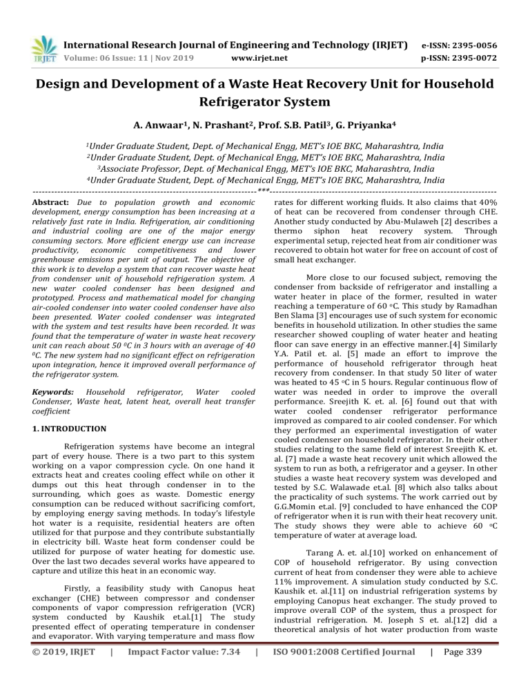
International Research Journal of Engineering and Technology (IRJET) e-ISSN: 2395-0056 Volume: 06 Issue: 11 | Nov 2019 p-ISSN: 2395-0072 www.irjet.net Design and Development of a Waste Heat Recovery Unit for Household Refrigerator System A. Anwaar1, N. Prashant2, Prof. S.B. Patil3, G. Priyanka4 1Under Graduate Student, Dept. of Mechanical Engg, MET’s IOE BKC, Maharashtra, India Graduate Student, Dept. of Mechanical Engg, MET’s IOE BKC, Maharashtra, India 3Associate Professor, Dept. of Mechanical Engg, MET’s IOE BKC, Maharashtra, India 4Under Graduate Student, Dept. of Mechanical Engg, MET’s IOE BKC, Maharashtra, India ------------------------------------------------------------------------***------------------------------------------------------------------------2Under Abstract: Due to population growth and economic development, energy consumption has been increasing at a relatively fast rate in India. Refrigeration, air conditioning and industrial cooling are one of the major energy consuming sectors. More efficient energy use can increase productivity, economic competitiveness and lower greenhouse emissions per unit of output. The objective of this work is to develop a system that can recover waste heat from condenser unit of household refrigeration system. A new water cooled condenser has been designed and prototyped. Process and mathematical model for changing air-cooled condenser into water cooled condenser have also been presented. Water cooled condenser was integrated with the system and test results have been recorded. It was found that the temperature of water in waste heat recovery unit can reach about 50 0C in 3 hours with an average of 40 0C. The new system had no significant effect on refrigeration upon integration, hence it improved overall performance of the refrigerator system. rates for different working fluids. It also claims that 40% of heat can be recovered from condenser through CHE. Another study conducted by Abu-Mulaweh [2] describes a thermo siphon heat recovery system. Through experimental setup, rejected heat from air conditioner was recovered to obtain hot water for free on account of cost of small heat exchanger. Keywords: Household refrigerator, Water cooled Condenser, Waste heat, latent heat, overall heat transfer coefficient 1. INTRODUCTION Refrigeration systems have become an integral part of every house. There is a two part to this system working on a vapor compression cycle. On one hand it extracts heat and creates cooling effect while on other it dumps out this heat through condenser in to the surrounding, which goes as waste. Domestic energy consumption can be reduced without sacrificing comfort, by employing energy saving methods. In today’s lifestyle hot water is a requisite, residential heaters are often utilized for that purpose and they contribute substantially in electricity bill. Waste heat form condenser could be utilized for purpose of water heating for domestic use. Over the last two decades several works have appeared to capture and utilize this heat in an economic way. Firstly, a feasibility study with Canopus heat exchanger (CHE) between compressor and condenser components of vapor compression refrigeration (VCR) system conducted by Kaushik et.al.[1] The study presented effect of operating temperature in condenser and evaporator. With varying temperature and mass flow © 2019, IRJET | Impact Factor value: 7.34 | More close to our focused subject, removing the condenser from backside of refrigerator and installing a water heater in place of the former, resulted in water reaching a temperature of 60 oC. This study by Ramadhan Ben Slama [3] encourages use of such system for economic benefits in household utilization. In other studies the same researcher showed coupling of water heater and heating floor can save energy in an effective manner.[4] Similarly Y.A. Patil et. al. [5] made an effort to improve the performance of household refrigerator through heat recovery from condenser. In that study 50 liter of water was heated to 45 oC in 5 hours. Regular continuous flow of water was needed in order to improve the overall performance. Sreejith K. et. al. [6] found out that with water cooled condenser refrigerator performance improved as compared to air cooled condenser. For which they performed an experimental investigation of water cooled condenser on household refrigerator. In their other studies relating to the same field of interest Sreejith K. et. al. [7] made a waste heat recovery unit which allowed the system to run as both, a refrigerator and a geyser. In other studies a waste heat recovery system was developed and tested by S.C. Walawade et.al. [8] which also talks about the practicality of such systems. The work carried out by G.G.Momin et.al. [9] concluded to have enhanced the COP of refrigerator when it is run with their heat recovery unit. The study shows they were able to achieve 60 oC temperature of water at average load. Tarang A. et. al.[10] worked on enhancement of COP of household refrigerator. By using convection current of heat from condenser they were able to achieve 11% improvement. A simulation study conducted by S.C. Kaushik et. al.[11] on industrial refrigeration systems by employing Canopus heat exchanger. The study proved to improve overall COP of the system, thus a prospect for industrial refrigeration. M. Joseph S et. al.[12] did a theoretical analysis of hot water production from waste ISO 9001:2008 Certified Journal | Page 339 International Research Journal of Engineering and Technology (IRJET) e-ISSN: 2395-0056 Volume: 06 Issue: 11 | Nov 2019 p-ISSN: 2395-0072 www.irjet.net heat of air conditioner. Implementation of a heat exchanger in the system has a potential for saving LPG gas. In an experiment R.B.Lokapure et. al.[13] found out that the COP of air conditioning system with heat exchanger for heat recovery increased about 13 percent. A comprehensive research on heat recovery systems carried out by Tanmay P. et. al. [14] Similarly Dhananjay P. et.al. [15] have reviewed on techniques of waste heat recovery and utilization. A.S.N Husainy et.al.[16] have also reviewed waste heat recovery systems but focusing on household refrigerators. Study by P. Elumalai et.al.[17] brings about a quite complex system of heat recovery using oven, water heater and pumps. Focus was to achieve complete utilization of waste heat. Lakshya Soni et.al.[18] Have also worked on waste heat recovery from refrigeration system and tried to improve the overall COP by factor of 2 of the system. S.A.Narnavne et.al.[19] used insulated heat box to use it as a mean to keep food, beverages and water warm. Fig -1: Arrangement for finding out amount of heat ejected by condenser of household refrigerator [1- flow meter, 2,3,4 – Digital temperature sensors, 5,6 – Pressure gauges] In this paper, the authors have put an effort to capture heat energy from condenser of household refrigerator. The original air cooled condenser coil of 230 liter refrigerator is removed and replaced by a new design and prototyped water cooled condenser. This new condenser coil is so designed that it work as an integral part of waste heat recovery unit (WHRU). This waste heat recovery unit is kept on the backside of the refrigerator. The heat get absorbed by water contained inside the tank of WHRU which can be utilized for various household purposes. Further an investigation carried out to study the effect of new condenser on the working of refrigerator with recovery of waste heat. 2.2. Mathematical model for changing an air cooled condenser in to water cooled ṁref = Mass flow rate of refrigerant R-134a: * LPH = flow rate of refrigerant lit/hr = density of refrigerant in kg/m3 ṁref = mass flow rate of refrigerant in m3/s Heat rejected by condenser (Qc): 2. METHODOLOGY It is also the heat absorbed by the surrounding water (Qw) The present work requires to calculate the amount of heat ejected by the condenser of household refrigerator. Qc = ṁref * (h2-h3) 2.1. Amount of heat rejected by air cooled condenser of the refrigerator h2 = Enthalpy of vapor refrigerant at condenser inlet h3 = Enthalpy of vapor refrigerant at condenser outlet For calculating the heat rejected by the original condenser following arrangements are made, | Impact Factor value: 7.34 Mass flow rate of water: Qw = ṁwater * Cpw *(T2-T1) Pressure gauges were attached at suction and discharge of compressor Flow meter was attached to obtain flow rate of refrigerant at the end of condenser Digital temperature sensors were used to obtain temperature of refrigerant at compressor suction, compressor discharge, condenser outlet and after expansion © 2019, IRJET Qc = Heat rejected in condenser in kJ/sec Qw = Heat absorbed by surrounding water in kJ/sec ṁwater = Mass flow rate of water in kg/sec Cpw = Specific heat of water in kJ/kgK = 4.187 kJ/kgK | ISO 9001:2008 Certified Journal | Page 340 International Research Journal of Engineering and Technology (IRJET) e-ISSN: 2395-0056 Volume: 06 Issue: 11 | Nov 2019 p-ISSN: 2395-0072 www.irjet.net Overall heat transfer coefficient: Overall heat transfer coefficient equation is used for new water cooled condenser dimensions. Taking into account the individual heat transfer coefficients of each streams, fouling factors and resistance of the pipe material. Qc = U0* Ao *∆Tm U0 = Overall heat transfer coefficient Uo = ( ) ( ) ( ( ) Sr. No. ΔTm = ( ) ( ) ( ( ) ) There are two parameters that need to be calculated for above equation, one is coefficient of convective heat transfer for inner surface (hi) and other coefficient of convective heat transfer for outer surface (ho) of the condenser. Depending on the type of flow of refrigerant, Reynolds number was used for the said purpose. Re = Reynolds Number: ref* V*Di /μ = 4* ṁref / π* Di T1 26.3 15.7 14.6 14.3 14.0 13.8 For Re >2000 Nu = 0.023*Re0.8*Pr0.3 Nu = 0.023* (4*ṁref /π*Di)0.8*(μCp /kref)0.3 = hi*Di/kref Final equation for convective heat transfer for inner surface, T2 29 36.3 50.3 68.2 71.9 14 T3 28 34 34 37 37 38 4. EXPERIMENTAL STUDY 4.1. Prototype of WHRU: Nusselt number: 0 7 8 9 9 10 Pressure (Bar) P1 P2 1.2 4.8 0.9 6.1 0.7 7 0.6 7.5 0.4 8.3 0.4 9.8 For WHRU a water tank is designed and fabricated based on the dimensions of the condenser so as to provide sufficient area for condenser coils to heat water inside. The leak proof water tank is made up of G.I. sheet with a capacity of 22 liters. An outer tank carries the water tank, both are separated from every side by a layer of glass wool for insulation. This helps contain the heat energy within the WHRU. Figure 2 and 3 shows the WHRU with its For Re <2000 Nu = 4.36 = hi * Di / kref hi = 4.36* kref / Di Impact Factor value: 7.34 T4 27 15.3 10.6 7.3 4.3 2 Flow (LPH) Mass flow rate of refrigerant (ṁref)=3.9217*10-3 kg/sec Heat rejected in condenser (Qc)= 0.84709 kW LMTD (∆Tm)= 20.856356 ºC Coefficient of Convective heat transfer for inner surface (hi) = 56742.2857 w/m2 k Coefficient Convective heat transfer for outer surface (ho) = 290.66 w/m2 k New length of water cooled condenser (L) = 7.3980 m hi = 0.023* (4* ṁref / π* Di)0.8*(μCp /k)0.3 * kref / Di | AND With the help of sensors as shown in figure 1, parameters such as temperature, pressure and flow rate were observed. Table 1 shows the observed data obtained from refrigerator. These observations were used in calculating the waste heat rejected by original condenser and the dimensions of new water cooled condenser. By using the methodology described above, calculation yielded values as follows, Nusselt number: © 2019, IRJET OBSERVATIONS Temperatures (ºC) 1 2 3 4 5 6 This equation was used to find the dimensions of new water cooled condenser. With this methodology one can use a copper tube of any diameter and use this equations to calculate the correct length of the condenser coil. This condenser coil interacts with the water medium and gives away heat to water, in other way it acts as a water heater. Table -1: Observation table for calculating dimensions of new condenser ∆Tm = Log Mean Temperature Difference (LMTD) (°C) * ho.= 4.36* kwater / Di 3. EXPERIMENTAL CALCULATIONS ) Ao = Heat transfer area of the condenser (m2) = 2π*ro*L Qc =(2π*ro*L) * Similarly coefficient of convective heat transfer for outer surface (ho): | ISO 9001:2008 Certified Journal | Page 341 International Research Journal of Engineering and Technology (IRJET) e-ISSN: 2395-0056 Volume: 06 Issue: 11 | Nov 2019 p-ISSN: 2395-0072 www.irjet.net components. This WHRU assembly is supported on a frame as shown in the figure 6. An off the shelf copper tube is used as a new condenser. It is checked for any leakage and placed inside the water tank in a way to cover most of the surface of water as shown in figure 2. Dimensions of both the tank are shown in figure 4 and 5. The process of prototyping has been recorded as presented in table 2 below. Fig -4: Dimensions of water tank Fig -2: Water cooled condenser coil in waste heat recovery unit [1-Outer tank, 2-Water tank, 3-New condenser coil, 4Glass wool, 5-Water] Fig -5: Dimensions of outer tank 4.2. Fabrication record of the system Table -2: Details of fabrication processes for waste heat recovery unit Parts produced Sheet cutting for tank Making of tanks Frame Condenser coil Fixation of condenser coil Fig -3: Waste heat recovery unit with inlet and outlet for water [6-Water Inlet, 7-Water Outlet] © 2019, IRJET | Impact Factor value: 7.34 | Operation Machine used Material used Time (min) Cutting Cutting machine G.I sheets 30 Bending, Forming Welding, Cutting , Grinding Hammer, Plier Welding gun ,Wheel cutter 90 M.S bars Bending, Cutting angle Copper Brazing Brazing machine Fixing the compressor Fitting with nut and bolts Drill Cutter Final brazing of copper coils Brazing Bending Brazing machine Attachment for sensors With the help of cello tape , 105 60 30 , ISO 9001:2008 Certified Journal Wooden ply 45 60 Temperature sensors | 30 Page 342 International Research Journal of Engineering and Technology (IRJET) e-ISSN: 2395-0056 Volume: 06 Issue: 11 | Nov 2019 p-ISSN: 2395-0072 www.irjet.net volume of water in the tank. Water bottles were used as a working load for refrigerator. Tests were carried out using water as a cooling medium for the condenser. Parameters such as pressure and flow of refrigerant is assumed to be same as that of original refrigerator. Running tests were carried out and temperature of water in the tank, outlet of compressor and condenser were studied for further analysis. Table 3 below shows various test conditions for the tests performed. 5.1. Test conditions 1 For loading the refrigerator 24 water bottles were kept in the refrigerator. Three different volume of water used in the tank L-1, L-2 and L-3 represented for 22 liter, 18 liters and 12 liters respectively. Readings for temperature were noted for 10 minutes interval. Fig -6: Final Prototype of the integrated system A household refrigerator of 230 liters capacity is used in this study. All the components of the refrigerator unit kept as it is except air cooled condenser, which is replaced by water cooled condenser (WHRU). Temperature sensor is dipped inside the water tank to measure the temperature of the water. Fig -7: Variation in outlet temperature of compressor with respect to time 5. EXPERIMENTAL RESULTS Table -3: Test conditions with variation in parameters Load on system 24 Water bottles (Full load) Test number Atmospheric temperature (0C) Volume of water (liters) Initial temperature of water (0C) Testing time (min) Date (dd/mm/yyyy) 1 25 2 24 3 26 12 Water bottles (Half load) 4 5 26 26 22 18 12 22 18 24 24 25 28 28 210 23/0 2/20 15 180 09/0 3/20 15 220 10/0 3/20 15 180 02/0 4/20 15 180 03/0 4/20 15 Refrigerator Capacity: 230 liters Fig -8: Variation in outlet temperature of condenser with respect to time A comprehensive experimental study was performed on the system. Total 6 round of tests were performed with changing parameters such as load on the refrigerator and © 2019, IRJET | Impact Factor value: 7.34 | ISO 9001:2008 Certified Journal | Page 343 International Research Journal of Engineering and Technology (IRJET) e-ISSN: 2395-0056 Volume: 06 Issue: 11 | Nov 2019 p-ISSN: 2395-0072 www.irjet.net As shown in figure 7 temperature of refrigerant at compressor exit kept increasing gradually. After a time period of around 60 minutes, temperature stabilized mainly due to high load at the start. For condenser outlet it took around 90 minutes to stabilize. No significant effect of initial temperature of water was observed as the nature of graph in figure 8 is same for all the 3 cases. Maximum temperature of refrigerant was around 39 0C, much lower than the saturation temperature of the liquid refrigerant at the given pressure. Which indicates refrigeration performance is not affected by the system. 5.2. Test condition 2 Load kept in the refrigerator is half i.e. 12 bottles were kept in the refrigerator. Three different volume of water used in the tank L-1, L-2 and L-3 represented for 22 liter, 18 liters and 12 liters respectively. The Readings for temperature were noted for 15 minutes interval. Fig -11: Variation in outlet temperature of compressor with respect to time From the figure 11, graph is more or less similar to the nature observed in test condition 1. Here it takes approximately 45 minutes to stabilize the temperature. For condenser outlet it took around 35 - 45 minutes to stabilize. Initial temperature of water has no significant effect on the performance. Figure 12 shows, maximum temperature of refrigerant was around 37 0C, much lower than the saturation temperature of the liquid refrigerant at the given pressure. Which indicates refrigerant in complete liquid form goes to the expansion device with no effect to refrigeration performance. Fig -9: Variation in water temperature with time As per the figure 9, graph shows that heat transfer rate is high at initial stage and diminishes as the temperature difference reduces between condenser and water. Water temperature inside the tank reaches up to 50 0C within 3 hours of running. There was some error in recording the power consumption reading, but it was constant throughout as shown in figure 10. Which indicates new condenser does not affects the performance of the original system and hence the energy consumption. Fig -12: Variation in outlet temperature of condenser with respect to time Fig -10: Variation in the power consumption with time © 2019, IRJET | Impact Factor value: 7.34 | ISO 9001:2008 Certified Journal | Page 344 International Research Journal of Engineering and Technology (IRJET) e-ISSN: 2395-0056 Volume: 06 Issue: 11 | Nov 2019 p-ISSN: 2395-0072 www.irjet.net Comments: Energy consumption of the overall system remained same. Hence a considerable electricity saving per year can be achieved for water heating. Tonnes of carbon emission for production of electricity and effect on global warming can be reduced REFERENCES [1] S.C. Kaushik, M. Singh, Feasibility and design studies for heat recovery from a refrigeration system with a canopus heat exchanger, Heat recovery system and CHP vol.15, no.7, pp.665-673,1995. Fig -13: Variation in water temperature with time Low temperature water absorbs the heat rejected by the condenser and refrigerant gets liquefied at the condenser exit. As per the figure 13, graph shows that heat transfer rate is high at initial stage and diminishes as the temperature difference reduces between condenser and water. Water temperature inside the tank reaches up to 45 0C within 3 hours of running. Out comes from all the tests are compiled in below table 4. Table -4: Experimental results obtained from test conducted on system [2] H.I. Abu-Mulaweh, Design and performance of a thermosiphon heat recovery system, Applied thermal engineering, 26, pp.471-477, 2006. [3] Ramdhane Ben Slama, Water-heater coupled with the refrigerator to develop the heat of the condenser, International Renewable Energy Congress, November pp. 5-7, 2009. [4] Romdhane Ben Slama, Refrigerator Coupling to a Water-Heater and Heating Floor to Save Energy and to Reduce Carbon Emissions, CWEEE, volume 2, pp.21-29, 2013. Time required (hour) 3 3 2 3hr 40min 3 3 [5] Y.A. Patil et. Al., Improving the Performance of Household Refrigerator by Recovering Heat from the Condenser, IJSR, volume 2, Issue 6, 2013. In this study a waste heat recovery unit was designed, prototyped and integrated with household refrigerator to generate hot water for household purposes. Since the water absorbs latent heat rejected by the condenser, waste heat rejected by the condenser is recovered. Maximum temperature of water in tank reached as high as 500C and the average temperature was around 400C. Energy consumption and performance of the overall system was unaffected due to the methodology used. The study successfully presents potential environmental friendly, energy efficient, cost effective alternative water heating system. [8] S.C. Walawade et.al., Design and Development of Waste Heat Recovery System for Domestic Refrigerator, OSRJMCE, pp. 28-32. © 2019, IRJET ISO 9001:2008 Certified Journal 22 18 15 Initial temperature of water (0C) 24 24 25 Final temperature of water (0C) 49 45 45 26 12 25 50 26 26 22 18 28 28 43 46 Sr. No. Tatm. 0C Volume (Liters) 1 2 3 25 24 26 4 *5 *6 [6] Sreejith K. Et.al., Experimental Investigation of a Household Refrigerator using Air-cooled and Watercooled Condenser, Research Inventy: IJES, Vol.4, Issue 6, PP 13-17, 2014. [7] Sreejith K. Et.al, Experimental Investigation of Waste Heat Recovery System for Household Refrigerator, Research Inventy: IJES, Vol.6, Issue.4, pp.19-23, 2016. 6. CONCLUSION | Impact Factor value: 7.34 | [9] G.G.Momin et.al., COP Enhancement of domestic refrigerator by recovering heat from the condenser, IJRAT, Vol.2, No.5, 2014. [10] Tarang A. Et. Al., Cost-Effective COP Enhancement of a Domestic Air Cooled Refrigerator using R-134a Refrigerant, IJETAE, Volume 4, Issue 11, November 2014 | Page 345 International Research Journal of Engineering and Technology (IRJET) e-ISSN: 2395-0056 Volume: 06 Issue: 11 | Nov 2019 p-ISSN: 2395-0072 www.irjet.net [11] S.C.Kaushik et. Al., Thermodynamic evaluation of heat recovery through a Canopus heat exchanger for vapor compression refrigeration (VCR) system, J Therm Anal Calorim, 110:1493–1499, 2012. [12] M. Joseh S. Et. Al., Efficient usage of waste heat from air conditioner, IJAET, Vol.4, issue 1, pp. 414-423, 2012. [13] R.B. Lokapure et. Al., Waste Heat Recovery through Air Conditioning System, IJERD, volume 5, Issue 3, pp. 8792, 2012. [14] Tanmay P. Et.al., A Review On Recovering Waste Heat From Condenser Of Domestic Refrigerator, IJSRM, vol.3, Issue.3, pp. 2409-2414, 2015. [15] Dhananjay P. Et.al., Review on study of waste heat utilization techniques in vapour compression refrigeration system, IRJET, volume 4, issue 7, pp. 2033-2039, 2017. [16] A.S.N. Husainy et.al., Review of Waste Heat Recovery from Household Refrigerator, Journal of research, volume 3, Issue 8, pp. 6-8, 2017. [17] P. Elumalai et.al., Experimental Study on Energy Recovery from Condenser Unit of Small Capacity Domestic Refrigerator, MEJSR, 23(3), pp. 417-420, 2015. [18] Lakshya Soni et.al., Waste heat recovery system from domestic refrigerator for water and air heating, IJESRT, 5(7), pp.700-705, 2016. [19] S.A. Narnavre et.al., Waste heat recovery system for refrigerator, ijariie, vol.5, issue 2, pp.2619-2625, 2019. © 2019, IRJET | Impact Factor value: 7.34 | ISO 9001:2008 Certified Journal | Page 346
