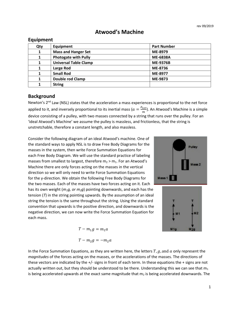
rev 09/2019 Atwood’s Machine Equipment Qty 1 1 1 1 1 1 1 Equipment Mass and Hanger Set Photogate with Pully Universal Table Clamp Large Rod Small Rod Double rod Clamp String Part Number ME‐8979 ME‐6838A ME‐9376B ME‐8736 ME‐8977 ME‐9873 Background Newton’s 2nd Law (NSL) states that the acceleration a mass experiences is proportional to the net force applied to it, and inversely proportional to its inertial mass (𝑎 ). An Atwood’s Machine is a simple device consisting of a pulley, with two masses connected by a string that runs over the pulley. For an ‘ideal Atwood’s Machine’ we assume the pulley is massless, and frictionless, that the string is unstretchable, therefore a constant length, and also massless. Consider the following diagram of an ideal Atwood’s machine. One of the standard ways to apply NSL is to draw Free Body Diagrams for the masses in the system, then write Force Summation Equations for each Free Body Diagram. We will use the standard practice of labeling masses from smallest to largest, therefore m2 > m1. For an Atwood’s Machine there are only forces acting on the masses in the vertical direction so we will only need to write Force Summation Equations for the y‐direction. We obtain the following Free Body Diagrams for the two masses. Each of the masses have two forces acting on it. Each has its own weight (m1g, or m2g) pointing downwards, and each has the tension (T) in the string pointing upwards. By the assumption of an ideal string the tension is the same throughout the string. Using the standard convention that upwards is the positive direction, and downwards is the negative direction, we can now write the Force Summation Equation for each mass. 𝑇 𝑚 𝑔 𝑇 𝑚 𝑔 𝑚 𝑎 𝑚 𝑎 In the Force Summation Equations, as they are written here, the letters 𝑇, 𝑔, and 𝑎 only represent the magnitudes of the forces acting on the masses, or the accelerations of the masses. The directions of these vectors are indicated by the +/‐ signs in front of each term. In these equations the + signs are not actually written out, but they should be understood to be there. Understanding this we can see that m1 is being accelerated upwards at the exact same magnitude that m2 is being accelerated downwards. The 1 reason m2 is being accelerated downwards is due to m2 having a larger weight than m1, and therefore there is a greater downwards acting force on m2 than m1. To solve for the magnitude of the acceleration that both masses will experience, we can simply use the substitution method by solving one equation for the tension T, then substituting that into the other equation. Let’s use the question for mass 1 to solve for the tension, then insert that into the equation for mass 2, then solve for the magnitude of the acceleration. 𝑇 𝑇 𝑚 𝑎 𝑚 𝑎 𝑚 𝑔 𝑚 𝑔 𝑚 𝑔 𝑚 𝑎 𝑚 𝑔 𝑚 𝑎 𝑚 𝑎 𝑚 𝑎 𝑚 𝑔 𝑚 𝑔 𝑎 𝑚 𝑚 𝑔 𝑚 𝑚 𝑎 𝑔 𝑚 𝑚 𝑚 𝑚 Here we see that the magnitude of the acceleration the two masses experience is given by the ratio of the difference of the two masses and the sum of the two masses all times gravitational acceleration. Since that ratio will always be less than 1, the acceleration will always be less than gravitational acceleration. As the ratio gets closer to 1, then the value of the acceleration of the masses approaches the value of gravitational acceleration. However, as the value of this ratio gets closer to zero, then the value of the acceleration approaches zero as well. Also, comparing this equation to NSL we get. 𝐹 𝑔 𝑚 𝑚 Here we see that the net force acting on each mass is equal to gravitational acceleration times the difference of the two masses. From the above algebra we can clearly see that 𝐹 𝑎 𝑚 𝑚 as well. 2 Setup 1. Using the provided equipment build the set show in the picture provided. Make sure that the photogate and pulley are horizontal. Thread the string through the pulley, then attach a hook to each end. 2. Make sure the PASCO 850 Interface is turned on. 3. Double click the Capstone Icon to open the Capstone Software. 4. In the Tool Bar, which is on the left hand side of the screen, click on the Hardware Setup icon to open the Hardware Setup window. There should be an image of the PASCO 850 interface in the Hardware Setup window. If it’s there, go to set 4. If it isn’t there, click on Choose Interface. The Choose Interface will open, and then select Passport, Automatically Detect, then click OK. 5. On the image of the PASCO 850 Interface click on the Digital Inputs Ch(1). A sensor list will appear. Scroll down and Photogate with Pulley. The Photogate with Pulley icon should now be shown connected to Digital Inputs Ch(1). Click on the Properties icon at the bottom right of the Hardware Setup window. The Properties window should open up. Make sure that the Spoke Arc Length (m) is set to 0.015000. If it isn’t, then set it to 0.015000, and then click OK. Plug the Photogate into Digital Inputs Ch(1) 6. Close the Tool Bar. 7. In the Displays Bar on the right side of the screen, double click the Graph icon. This will cause a graph to appear in Page #1. For the y‐axis click on Select Measurement, then select Linear Speed (m/s). The computer will automatically select Time (s) for the x‐axis. 3 Procedure: Constant Total Mass 1. To one hook add 80.0 g, and to the other add 10.0 g. Each hook itself has a mass of 5.0 g so that means we now have 85.0 g on one end of the string and 15.0 g on the other end. The larger mass with be called m2, and the smaller mass will be called m1. (The masses of the hooks themselves MUST be taken into consideration.) 2. Slowly pull down on m1 so that m2 is about near the pulley, and m1 is near the table top. 3. At the bottom left of the screen click on the big red circle to start recording data. Wait about 1 second and then let go of m1. After m2 stops falling downwards click on the big red square at the bottom left of the screen to stop recording data. 4. At the top left of Page #1 click on the Highlight Data icon. The Highlight box should appear on the graph. Move and scale the highlight box such that only the data points that represent the moments when the masses were falling are highlighted. (You might have to scale the graph as well.) Click on the down arrow next to the applied selected curve fit icon to open the list of best fit curves. Select the linear fit. The magnitude of the slope of the line is the magnitude of the acceleration the masses experienced. (The slope will be positive or negative depending on the direction of rotation of the pulley.) Record, in the Constant Total Mass Table, the experimental acceleration (aex) for Run 1. 5. Repeat sets 1 through 4 for the rest of the mass combinations listed in the Constant Total Mass Table. Keep in mind that each of the hooks have a mass of 5.0 g, and it must be taken into consideration. Procedure: Constant Net Force 6. To one hook add 60.0 g, and to the other add 30.0 g. Each hook itself has a mass of 5.0 g so that means we now have 65.0 g on one end of the string and 35.0 g on the other end. The larger mass with be called m2, and the smaller mass will be called m1. (The masses of the hooks themselves MUST be taken into consideration.) 7. Slowly pull down on m1 so that m2 is about near the pulley, and m1 is near the table top. 8. At the bottom left of the screen click on the big red circle to start recording data. Wait about 1 second and then let go of m1. After m2 stops falling downwards click on the big red square at the bottom left of the screen to stop recording data. 9. At the top left of Page #1 click on the Highlight Data icon. The Highlight box should appear on the graph. 4 Move and scale the highlight box such that only the data points that represent the moments when the masses were falling are highlighted. (You might have to scale the graph as well.) Click on the down arrow next to the applied selected curve fit icon to open the list of best fit curves. Select the linear fit. The magnitude of the slope of the line is the magnitude of the acceleration the masses experienced. (The slope will be positive or negative depending on the direction of rotation of the pulley.) Record, in the Constant Net Force Table, the experimental acceleration (aex) for Run 6. 10. Repeat sets 1 through 4 for the rest of the mass combinations listed in the Constant Net Force Table. Keep in mind that each of the hooks have a mass of 5.0 g, and this mass must be included in the values of m1 and m2. 5 Analysis of Atwood’s Machine Lab Name______________________________________________ Group#________ Course/Section_______________________________________ Instructor____________________________________________ Constant Total Mass Table (10 points) Run 1 2 3 4 5 m1(kg) 0.0150 0.0200 0.0250 0.0300 0.0350 m2(kg) 0.0850 0.0800 0.0750 0.0700 0.0650 m1+m2 aex(m/s2) Fnet(N) ath(m/s2) % Error Complete the above chart. Use the experimental acceleration to calculate the net force, and find the % error between the theoretical acceleration and the experimental acceleration for each run. 6 Constant Net Force Table (10 points) Run 1 2 3 4 5 m1(kg) 0.0350 0.0400 0.0450 0.0500 0.0550 m2(kg) 0.0650 0.0700 0.0750 0.0800 0.0850 m1+m2 aex(m/s2) Fnet(N) ath(m/s2) % Error Complete the above chart. Use the experimental acceleration to calculate the net force, and find the % error between the theoretical acceleration and the experimental acceleration for each run. 7 1. What is a real world application of an Atwood's Machine? (5 points) 2. What are some reasons that would account for the percent error calculated above? (5 points) 3. For the Constant Total Mass data (Table 1), plot a graph of Fnet vs. aexp, and find the slope of the best fit line for the data. (12 points) 4. (a) What are the units of the slope? (3 points) (b) What physical quantity does the slope of the best-fit line represent? (5 points) (c) Calculate the % Error between this quantity and your slope. (3 points) 5. For the Constant Net Force data (Table 2), plot a graph of aexp vs 1/Mtot, and find the slope of the best fit line for the data. (12 points) 6. (a) What are the units of the slope? (3 points) (b) What physical quantity does the slope of the best-fit line represent? (5 points) (c) Calculate the % Error between this quantity and your slope. (3 points) 8 7. Explain how the Force vs. Acceleration plot relates to Newton’s Second Law. (4 points) 8. In this experiment, we made the assumption that the tension and the acceleration experienced by the two subsystems (the two hangers) were exactly the same. Why are these good and/or valid assumptions? (5 points) 9. Where does the greatest source of our percent error come from? (5 points) 10. Above, we derived an equation for the acceleration: 𝑎 . Briefly explain what the numerator and denominator are in a physical sense. (5 points) 11. Do the results of our experiment confirm theoretical predictions? On what do you base your answer? (5 points) 9
