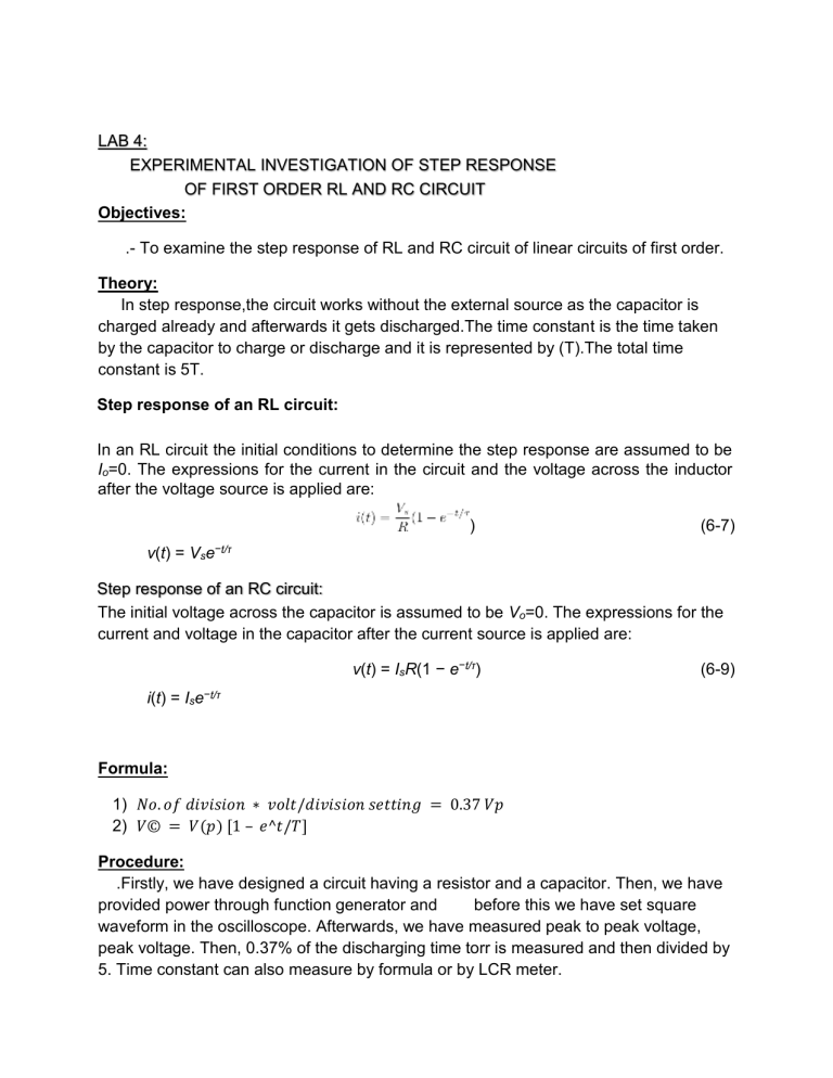
LAB 4: EXPERIMENTAL INVESTIGATION OF STEP RESPONSE OF FIRST ORDER RL AND RC CIRCUIT Objectives: .- To examine the step response of RL and RC circuit of linear circuits of first order. Theory: In step response,the circuit works without the external source as the capacitor is charged already and afterwards it gets discharged.The time constant is the time taken by the capacitor to charge or discharge and it is represented by (T).The total time constant is 5T. Step response of an RL circuit: In an RL circuit the initial conditions to determine the step response are assumed to be Io=0. The expressions for the current in the circuit and the voltage across the inductor after the voltage source is applied are: ) (6-7) v(t) = Vse−t/τ Step response of an RC circuit: The initial voltage across the capacitor is assumed to be Vo=0. The expressions for the current and voltage in the capacitor after the current source is applied are: v(t) = IsR(1 − e−t/τ) (6-9) i(t) = Ise−t/τ Formula: 1) 𝑁𝑜. 𝑜𝑓 𝑑𝑖𝑣𝑖𝑠𝑖𝑜𝑛 ∗ 𝑣𝑜𝑙𝑡/𝑑𝑖𝑣𝑖𝑠𝑖𝑜𝑛 𝑠𝑒𝑡𝑡𝑖𝑛𝑔 = 0.37 𝑉𝑝 2) 𝑉© = 𝑉(𝑝) [1 – 𝑒^𝑡/𝑇] Procedure: .Firstly, we have designed a circuit having a resistor and a capacitor. Then, we have provided power through function generator and before this we have set square waveform in the oscilloscope. Afterwards, we have measured peak to peak voltage, peak voltage. Then, 0.37% of the discharging time torr is measured and then divided by 5. Time constant can also measure by formula or by LCR meter. Same is the steps followed for the inductor as well. Diagrams: Calculations: capacitor: V(p-p) = 10V V(p) = 5V 0.37 * V(p) = 1.85 T = R * C = 9.011 Inductor: V(p-p) = 8.4V V(p) =4.2V 0.37 * 4.2 = 1.554 no. of division = 7.77 T = L/R = 1.5u Conclusions: we have completed our open ended lab and got to know experimental verification of step response of circuit of resistance, capacitor and inductor.


