Turbojet Thrust
advertisement

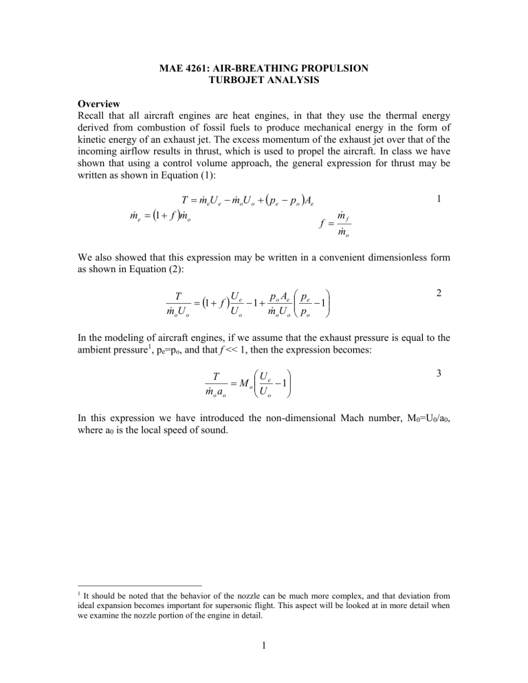
MAE 4261: AIR-BREATHING PROPULSION TURBOJET ANALYSIS Overview Recall that all aircraft engines are heat engines, in that they use the thermal energy derived from combustion of fossil fuels to produce mechanical energy in the form of kinetic energy of an exhaust jet. The excess momentum of the exhaust jet over that of the incoming airflow results in thrust, which is used to propel the aircraft. In class we have shown that using a control volume approach, the general expression for thrust may be written as shown in Equation (1): eU e m oU o pe po Ae T m m e 1 f m o 1 f m f m o We also showed that this expression may be written in a convenient dimensionless form as shown in Equation (2): U p A T 1 f e 1 o e m oU o Uo m oU o pe 1 po 2 In the modeling of aircraft engines, if we assume that the exhaust pressure is equal to the ambient pressure1, pe=po, and that f << 1, then the expression becomes: U T M o e 1 m o ao Uo 3 In this expression we have introduced the non-dimensional Mach number, M0=U0/a0, where a0 is the local speed of sound. 1 It should be noted that the behavior of the nozzle can be much more complex, and that deviation from ideal expansion becomes important for supersonic flight. This aspect will be looked at in more detail when we examine the nozzle portion of the engine in detail. 1 We represent a gas turbine engine using a Brayton cycle and are able to derive expressions for work as functions of temperature (or pressure) at various points in the cycle. We now seek to perform an ‘ideal cycle analysis’, which is a method for expressing thrust and thermal efficiency of engines in terms of useful design variables. The objective of cycle analysis for various propulsion devices (ramjets, turbojets, turbofans) is to estimate the thrust, T, and the thermal efficiency, thermal (or alternatively Isp) as a function of (1) typical design limiters, (2) flight conditions, and (3) design choices so that we can analyze the performance of various engines2. To do so, we will employ the following methodology: 1. Estimate the ingested mass flow, m o , and the exhaust to inlet velocity ratio, Ue/Uo in terms of temperature ratios. 2. Use a power balance to relate turbine parameters to compressor parameters. 3. Use an energy balance across the burner (combustor) to relate the combustor temperature rise to the fuel flow rate and fuel energy content. We can write the ratio of exhaust to inlet velocity ratio as: Ue Me Uo Mo RTe RTo Me Mo Te To It is most efficient to find the exit Mach number and temperature by keeping track of the stagnation temperatures and pressures through all engine components. In general, it is the stagnation properties that most conveniently represent the effect of the components on the fluid as it flows through the engine. The relations for stagnation temperature and pressure are given below3: Tt 1 2 1 M T 2 pt 1 2 1 1 M p 2 2 Note that ideal cycle analysis addresses only the thermodynamics of the airflow within the engine and does not concern itself with the detailed design of the components, such as blading, rotational speed, or any other geometry. Instead the analysis is focused on the results that the various components produce, such as temperature and pressure ratios. Later in the course we will look at the detailed geometry and operation of these components to see how they work to produce given results. 3 The terms stagnation temperature and total pressure are synonyms, meaning exactly the same thing. In this document stagnation temperatures and pressures are denoted by T t and pt, respectively. In other texts, such as Mechanics and Thermodynamics of Propulsion, by Hill and Peterson, the stagnation temperature and pressure are denoted by T 0 and p0, respectively. Both forms of the notation are common in the literature. 2 Notation and Station Numbering It is very helpful to define a set of symbols that represent ratios of stagnation properties as distinguished from static or thermodynamic properties of the gas. Also note that stagnation properties, Tt and pt, are more easily measured than static properties (T and p). The table below summarizes this set of useful symbols: Table 1: Summary of Useful Notation Symbol Physical Description Ratio of stagnation (total) pressures across component (d: diffuser (inlet), c: compressor, b: burner (combustor), t: turbine, a: afterburner, n: nozzle) Ratio of stagnation (total) temperatures across component (d: diffuser (inlet), c: compressor, b: burner (combustor), t: turbine, a: afterburner, n: nozzle) Ratio of stagnation (total) pressure to ambient static pressure, p0 Ratio of stagnation (total) temperature to ambient static temperature, T0 The flow upstream of the engine may be written as: Tt 0 1 2 1 M 0 0 T0 2 pt 0 1 2 1 1 M0 0 p0 2 1 1 0 0 0 0 Ideal Assumptions: Inlet or Diffuser: d=1, d=1 (adiabatic, isentropic) Combustor or Burner and Afterburner: b=1, a=1 Nozzle: n=1, n=1 For the compressor and for the turbine we can write: pt 3 c pt 2 pt 5 t pt 4 Tt 3 c Tt 2 Tt 5 t Tt 4 1 c c 1 t t The turbine inlet temperature is given by: Tt 4 t To This quantity is used so frequently that it gets its own special designation, t. It is also one of the most important metrics for aircraft engine performance. 3 Turbojet Analysis A cut-away picture of the General Electric J79 turbojet engine is shown below: Figure 1: GE J79 Turbojet Engine (http://www.aircraftenginedesign.com). The engine was used on the Convair B-58 "Hustler", the first US bomber capable of maintaining speeds in excess of Mach 2. The J79 also was used on some fighters developed during the late 1950's. The two most famous examples are the McDonnell Douglas F-4 and Lockheed F-104, both capable of flying at Mach 2. The schematic for the turbojet from Hill & Peterson is shown below in Figure 2a: Figure 2a: Turbojet Schematic from Mechanics and Thermodynamics of Propulsion, 2nd Edition (Figure 5.14) Another schematic which depicts the same station numbers as well as the nomenclature used in Table 1 is shown below in Figure 2.b: Figure 2.b: Schematic of Turbojet Engine using Nomenclature from Table 1. Note that in Figure 2.b, the nomenclature used for the inlet mass flow rate is m o , the fuel flow rate is m f , and finally the afterburner fuel flow rate is m a . 4 We can now use the notation from Table 1 to develop expressions for the Thrust, T, and Specific Impulse, Isp, of the turbojet engine. For this engine, we can write4: Ue U7 M7 Uo Uo Mo RT7 RTo M7 Mo T7 To We begin the procedure by tracking the changes of stagnation temperature and pressure through the engine and recalling that: Tt 7 1 2 1 M7 T7 2 Tracking temperatures through the engine: T T T T T T T Tt 7 Tto t1 t 2 t 3 t 4 t 5 t 6 t 7 Tt 0 Tt1 Tt 2 Tt 3 Tt 4 Tt 5 Tt 6 T T T T T Tt 7 Tt 0 t 2 t 3 t 4 t 5 t 7 Tt 0 d c b t n Tt 0 Tt 2 Tt 3 Tt 4 Tt 5 1 2 Tt 7 T0 1 M 0 c b t T0 0 c b t 2 1 2 Tt 7 T7 1 M 7 To o c b t To t t 2 4 Equation (4) expresses the exit temperature as a function of the inlet temperature, the Mach number, and the temperature changes across each component. In the same way we can perform the pressure accounting through the engine: 1 2 1 pt 7 p7 1 M 7 po o c b t n 2 5 If p7=po (assumption of an ideally expanded nozzle) and if b ~ 1 (constant pressure heat addition), then we can write: 1 2 1 M 7 0 c t 1 2 Now, we equate the expressions from Equations 4 and 5 to give: 4 Note the approximation in this expression. Again, we are dealing with ideal cycle analysis, so we will assume that specific heat ratios and gas constants remain fixed throughout the engine. 5 1 1 2 M 7 o c t o c t 1 2 2 o c t 1 M 72 1 6 It is important to realize that although this expression for the exit Mach number is written in terms of temperature ratios, it comes from the pressure change in the engine. This is a general result, namely that the exit Mach number depends on the ratio of jet stagnation pressure to the ambient pressure, not at all on the temperature. From Equation (4): T7 T7 Tt 7 0 c b t b To Tt 7 T0 0 c t U7 M7 Uo M0 0 1 1 2 2 1 M0 T7 T0 0 c t 1 M 02 M 02 b 2 0 1 1 So far these are general expressions are applicable to any gas stream. We now substitute them into the expression for the velocity ratio and the thrust: U7 U0 0 c t 1 b 0 1 Note that the above expression is identical to Equation 5.45 in Hill & Peterson, with the proviso that nozzle adiabatic efficiency is unity and that the specific heat ratio within the nozzle is simply . This expression can be further simplified using the results from Equations (4) and (5) as: T7 b To U7 U0 1 t t 1 2 M 72 t o c 2 o c t 1 t 1 o c Mo 7 Finally the thrust per unit mass flow (times the speed of sound to make it dimensionless) is: 6 T 2 o c t 1 t m o ao 1 o c M o 8 We now have two steps left. The first step is to write c in terms of t by noting that they are related by the condition that the power used by the compressor is equal to the power provided by the turbine, which is called the power balance. The second step is to perform an energy balance across the combustor to arrive at expressions for specific impulse, thrust specific fuel consumption, and overall efficiency. Power Balance Between Turbine and Compressor: So far we have not made these expressions particular to the turbojet engine, because we have not included the relationship between the compressor and the turbine. In the turbojet engine the turbine is connected to the compressor by a shaft, and hence the turbine power equals the compressor power. We can arrive at this expression starting with the steadyflow energy equation: m ht q w s ht = - rate of shaft work Assuming that the compressor and turbine are adiabatic, then m done by the system = rate of shaft work done on the system. Since the turbine shaft is connected to the compressor shaft: m c p Tt 3 Tt 2 m c p Tt 4 Tt 5 Tt 3 T T T 1 t 2 t 4 1 t 5 Tt 2 To To Tt 4 0 c 1 t 1 t t 1 o c 1 t 9 So, finally for the turbojet engine we have the thrust equation: T 2 t o c 1 t m o ao 1 o c T 2 1 t 1 m o a o 1 o c M o 0 c 1 M o 10 We are also interested in the fuel consumption. Again, using the definition of specific impulse: 7 I sp T T m f g m o fg Energy (Heat) Balance Across the Burner (Combustor): The final step involves writing the specific impulse, thrust specific fuel consumption and other measures of efficiency using these same parameters. We begin by writing the First Law across the combustor to relate the fuel flow rate and heating value of the fuel to the total enthalpy rise: m f h m o c p Tt 4 Tt 3 m f m o c p To h t o c So, we can write the specific impulse as: I sp T ha o m o a o gc T o c p o t 11 This is the desired result. We have expressed the specific impulse in terms of typical design parameters, such as the flight Mach number, design variables and fuel and atmospheric properties. The overall efficiency of an aircraft engine was given as: overall TU 0 m f h Substituting from above, we may show that: overall T M 0 1 m 0 a 0 t c 0 8


