1 CHAPTER 7: ELECTRICITY AND MAGNETISM 7.1
advertisement

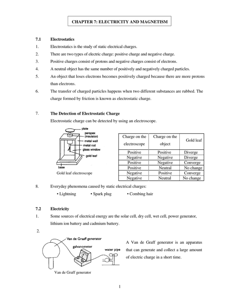
CHAPTER 7: ELECTRICITY AND MAGNETISM 7.1 Electrostatics 1. Electrostatics is the study of static electrical charges. 2. There are two types of electric charge: positive charge and negative charge. 3. Positive charges consist of protons and negative charges consist of electrons. 4. A neutral object has the same number of positively and negatively charged particles. 5. An object that loses electrons becomes positively charged because there are more protons than electrons. 6. The transfer of charged particles happens when two different substances are rubbed. The charge formed by friction is known as electrostatic charge. 7. The Detection of Electrostatic Charge Electrostatic charge can be detected by using an electroscope. Gold leaf electroscope 8. Charge on the Charge on the electroscope object Positive Negative Positive Positive Negative Negative Positive Negative Negative Neutral Positive Neutral Gold leaf Diverge Diverge Converge No change Converge No change Everyday phenomena caused by static electrical charges: • Lightning • Spark plug • Combing hair 7.2 Electricity 1. Some sources of electrical energy are the solar cell, dry cell, wet cell, power generator, lithium ion battery and cadmium battery. 2. A Van de Graff generator is an apparatus that can generate and collect a large amount of electric charge in a short time. Van de Graff generator 1 3. An electric current (I), is defined as the rate of flow of electrons. 4. The electrical force needed to move electrons between two points is called the voltage (V) or potential difference between the two points. 5. The property of a materials that prevents or resists the flow of electrons through the material is called the resistance (R). 7.3 Electric Current, Voltage and Resistance Electrical Current quantity Quantity of electric The potential charge that flows difference between two flow of electric through a conductor points in an electric in circuit Definition Measuring instrument Voltage Ammeter Voltmeter Resistance The opposition to the charge Using Ohm's Law R= V I Symbol I V R Simple circuit Resistance of wire Method of connection depends on: Series Parallel • length • diameter • type of metal • temperature 7.4 Relationship between current, voltage and resistance 1. Ohm’s Laws states that the current flowing through a conductor is directly proportional to its voltage. 2. Ohm’s law is given by the following formula, Voltage (V) V = Resistance (Ω) Currents (A) = R , I 2 7.5 Parallel and Series Circuits Series circuit Difference in term Parallel circuit Type of circuit The electrical components are connected end to end The current flows in one channel only The other bulbs will not light up Same in every resistance I = I1 = I2 = I3 Method of connection Number of channels If one bulb burns out are connected side by side The current flows in more than one channel The other bulbs will still light up Same as the total amount of Amount of current current in every channel I=I1 + I2 + I3 Same as the amount of voltage through every bulb The electrical components Voltage is the same as the Amount of voltage V = VI + V2 + V3 voltage supply V1 = V2 = V3 = V Total resistance (R) is Total resistance (R) is the same as total of all resistances calculated as follows: Amount of resistance R=RI+R2+R3 1=1+1 +1 R RI R2 R3 Does not last long Lifespan Increases if the number of Current cells increases 3 Lasts long Same even though the number of cells increases 7.6 Magnetism 1. Magnetism is a group of phenomena associated with magnetic fields. 2. The characteristics of a magnet are: (a) A magnet has two poles – the north and the south poles. (b) The same poles repel, different poles attract each other. (c) A free hanging magnet always points in the north-south direction. (d) A magnet can attract iron, steel, cobalt and nickel. 3. A magnetic field is a field of force surrounding a magnetic body. 7.7 Electromagnetism 1 An electromagnet is a temporary magnet formed when an electric current is passed Through a coil of conductor wire. 2 The current that flows through the conductor produces a magnet field around it 3 The direction of the magnetic field of a straight wire can be determined by using the RIGHT HAND GRIP RULE. a. The thumb represents the direction of the current flow b. The curved fingers represent the direction of the magnetic field 4. The strength of a solenoid magnetic field can be increased by a. increasing the number of turns in the coiled wire. b. Inserting a laminated iron bar into the solenoid. c. Increasing the current flow. 5. Electromagnets are used in loud speakers, electric bells, telephone receivers and telegraph machines. 6. The strength of a solenoid magnetic field can be increased by d. increasing the number of turns in the coiled wire. e. Inserting a laminated iron bar into the solenoid. f. Increasing the current flow. 4


