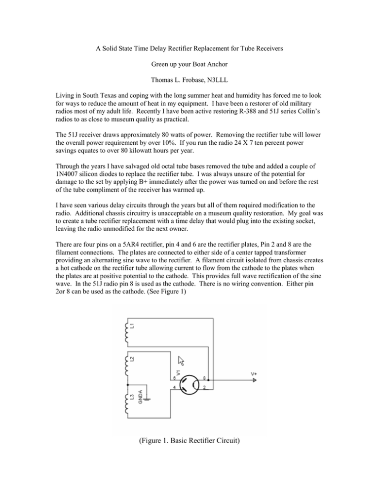
Figure 1. Basic Rectifier Circuit
advertisement

A Solid State Time Delay Rectifier Replacement for Tube Receivers Green up your Boat Anchor Thomas L. Frobase, N3LLL Living in South Texas and coping with the long summer heat and humidity has forced me to look for ways to reduce the amount of heat in my equipment. I have been a restorer of old military radios most of my adult life. Recently I have been active restoring R-388 and 51J series Collin’s radios to as close to museum quality as practical. The 51J receiver draws approximately 80 watts of power. Removing the rectifier tube will lower the overall power requirement by over 10%. If you run the radio 24 X 7 ten percent power savings equates to over 80 kilowatt hours per year. Through the years I have salvaged old octal tube bases removed the tube and added a couple of 1N4007 silicon diodes to replace the rectifier tube. I was always unsure of the potential for damage to the set by applying B+ immediately after the power was turned on and before the rest of the tube compliment of the receiver has warmed up. I have seen various delay circuits through the years but all of them required modification to the radio. Additional chassis circuitry is unacceptable on a museum quality restoration. My goal was to create a tube rectifier replacement with a time delay that would plug into the existing socket, leaving the radio unmodified for the next owner. There are four pins on a 5AR4 rectifier, pin 4 and 6 are the rectifier plates, Pin 2 and 8 are the filament connections. The plates are connected to either side of a center tapped transformer providing an alternating sine wave to the rectifier. A filament circuit isolated from chassis creates a hot cathode on the rectifier tube allowing current to flow from the cathode to the plates when the plates are at positive potential to the cathode. This provides full wave rectification of the sine wave. In the 51J radio pin 8 is used as the cathode. There is no wiring convention. Either pin 2or 8 can be used as the cathode. (See Figure 1) (Figure 1. Basic Rectifier Circuit) When solid state rectifiers are substituted the diode anodes are connected in place of the tube plates and the cathodes are tied together to provide full wave rectification just as in the tube circuit, leaving the 5 volt filament unused. As I thought through my options for a solid state delay, circuit the unused 5 volt filament winding became a method to separately power a timer circuit. The caveat was circuit had to float on top of the radio’s high voltage, making Pin 8 common 220 VDC above ground. This would allow me to preserve the original tubes pin connectivity. In order to test the concept I made a breadboard on top of an old tube base creating a positive half wave rectifier by tying a diode from the unused side 5 volt filament winding, pin 2 of the tube base into a 1000UF capacitor whose negative was the other side of the filament winding, pin 8 of the tube base. In turn the top of relay coil was wired to the positive side of the half wave rectifier and the return side of the coil was connected to an insulated toggle switch. The anodes of two solid state diodes were connected from pin 4 and pin 6 of the tube base. The cathodes were connected to the normally open relay contact. The common contact was connected to pin 8 of the tube base. I successfully switched the high voltage through the relay switched from a supply floating on the high voltage. (See Figure 2) (Figure 2. Test Circuit) I have migrated to the ATMEL AVR family of processors for my home projects. Atmel provides state of the art tools at prices affordable for hobbyists and amateurs. I chose an ATMEL AVR Tiny13, 8 pin microprocessor, to provide the timing function. This device allowed me to do timing and control functions with out the need for any peripheral components, keeping the circuit simple. It has finally become cost effective to replace a 555 timer with a microprocessor, believe it or not! Four empirical times were derived for delay. A set of jumpers have been added to select one of these four discrete timer values. In order to minimize the shock to the filter capacitors a dropping resistor was added to the circuit that would provide a time constant between the B+ source and the filter capacitors. A second relay is provided to bypass the resistor once the filter capacitor is charged. Two digital outputs have been defined on the Atmel Tiny13, one for K1 the delay B+ relay and the second to remove the series dropping resistor from the circuit. These relays are driven through a pair of VN10KM N channel FET’s. The Tiny13 requires a regulated power supply. A 5 volt, 3 terminal, regulator was provided to provide for this requirement. A .5 amp fuse has also been added to protect the transformer in case of a short in the radio. The Tiny13’s job is very simple, it wakes up, checks the jumpers to determine which delay to use, starts the delay timer and waits. Once the timer is expired, the Tiny13 closes K2 to add the series resistance to the B+ circuit and then closes K1 to apply the B+ to the circuit. After approximately 1 second K2 opens removing the series resistance from the circuit. It the passes into a sleep mode until the radio power is cycled. Care must be taken not to touch any portion of this device while the radio is powered on or the radio’s filter capacitors are charged. This project is for the experienced amateur, high voltage can be lethal. (Figure 3. Final Schematic) (Figure 4. Circuit Board Layout) (Figure 5. Prototype Replacement)


