AeroAntenna Technology, Inc.
20732 Lassen Street, Chatsworth, CA 91311
Phone: (818) 993-3842
Fax: (818) 993-4525
IsatPhone 2
Vehicular Antenna Kit
Antenna Model Number: AT1595-92
User Manual
© 2015 AeroAntenna Technology, Inc. All Rights Reserved.
AT15959284-01_4
IsatPhone 2 Vehicular Antenna Kit User Manual
1 Important Safety Information: Exposure to RF Signals
This device complies with Part 15 of the FCC Rules. Operation is subject to the
following two conditions: (1) this device may not cause harmful interference
and (2) this device must accept any interference received, including
interference that may cause undesired operation.
WARNING
To satisfy FCC RF exposure requirements for mobile
transmitting devices, the minimum safety distance is
55 cm (21.7 inches). This separation distance should
be maintained between antenna and people during
operation of the antenna.
WARNING
MICROWAVE RADIATION
MINIMUM SAFE DISTANCE
0.55 METRES
2 Introduction
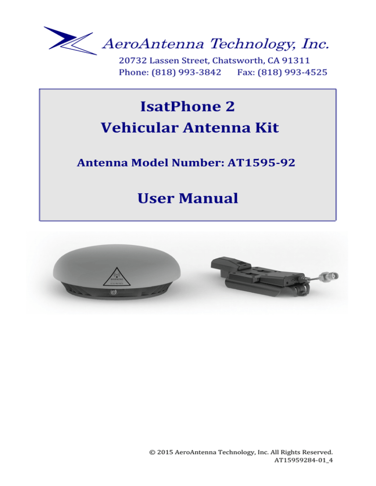
The Vehicular Antenna (AT1595-92) is an accessory designed for use with the
IsatPhone 2 on land vehicles. When the IsatPhone 2 is connected to the
antenna it is possible for a user to maintain a link to the satellite while making
calls in a moving or stationary land vehicle. The antenna requires DC power
provided via USB cable from car charger to the bottom of the clip adapter.
3 Antenna Kit Contents
suction cup
mount
clip adapter
AT1595-92 antenna
dual USB
car charger
(2) USB
cables
RF cable
page 2 of 7
spanner/wrench
© 2015 AeroAntenna Technology, Inc. All Rights Reserved.
4 Connecting Your Antenna
4.1 Connect power to clip adapter via USB cable
The antenna requires power which comes from
the car charger. For your convenience a dual
USB car charger is provided in the kit so that
you can simultaneously power/charge the
IsatPhone 2 and power the antenna.
micro USB
Insert the car charger into the cigarette
receptacle
lighter/12VDC power outlet in your vehicle.
Plug one end of the USB cable into the car
charger. Plug the other end into the micro-USB receptacle on the bottom of
the clip.
4.2 Connect cable to antenna
Connect RF cable to the antenna. Use the supplied wrench/spanner to ensure a
good connection.
4.3 Place antenna on roof of vehicle
For best results the antenna should be positioned on a flat portion of the roof
of the car where it will have a clear, unobstructed view of the sky in all
directions. Further, for optimal performance the antenna should be placed
away from the edge of the roof and towards the center.
4.4 Route cables into vehicle
The cables can now be routed into the vehicle. In many vehicles, the door
seals are sufficiently pliable that they will not damage the cables when the
door is closed.
4.5 Connect RF cable to clip adapter
4.6 Open Rear Connector Access Panel
Open rear connector access panel (see figure below).
1
2
3
4
© 2015 AeroAntenna Technology, Inc. All Rights Reserved.
page 3 of 7
IsatPhone 2 Vehicular Antenna Kit User Manual
4.7 Connect handset to clip adapter
Connect the handset to the clip adapter as shown below
click
2
3
1
4.8 Suction cup mount
A suction cup mount is included in
the kit for use with the clip
adapter. The suction cup can be
mounted to a window or other flat
surface and will hold the phone
securely for hands-free
communication and while
charging via the car charger.
2
1
1. Insert rectangular tabs on
suction cup mount into clip
adapter
2. Slide tabs up to lock into
place
page 4 of 7
© 2015 AeroAntenna Technology, Inc. All Rights Reserved.
4.9 Alternative mounting options
The clip adapter also has 4 mounting holes in a standard AMPS pattern
(30mm×38 mm center to center hole pattern) for use with other mounts. As a
precaution, verify printed dimensions before drilling.
[1.18 in]
30mm
[1.50in]
38mm
© 2015 AeroAntenna Technology, Inc. All Rights Reserved.
page 5 of 7
IsatPhone 2 Vehicular Antenna Kit User Manual
5 Specifications
Mobile or Fixed Base Station
EQUIPMENT TYPE
CE Mark,
Yes
INTEGRATED OPERATING
ENVIRONMENT
[ x ] Commercial
[ x ] Light Industry & Heavy Industry
POWER SUPPLY REQUIREMENT
9 to 36V DC, 30W maximum
RF INPUT POWER RATING
(US & CANADA)
30 dBm or 1.0 Watt peak
(conducted)
EIRP
10.93 dBW Max
DUTY CYCLE
N/A
TX OPERATING
FREQUENCY RANGE
1626.5 – 1660.5 MHz
RX OPERATING
FREQUENCY RANGE
1525.0 – 1559.0 MHz
RF INPUT IMPEDANCE
50 Ohms
MODULATION
G1W
EMISSION DESIGNATION
86K1G1W
ANTENNA TYPE
Integral
ANTENNA CONNECTOR TYPE
Inmarsat: SMA (Female)
GPS:
SMA(Female)
TEMPERATURE RATING
STORAGE:
OPERATIONAL:
page 6 of 7
-40°C to +80°C
-25°C to +55°C
© 2015 AeroAntenna Technology, Inc. All Rights Reserved.
~~NOTES~~
© 2015 AeroAntenna Technology, Inc. All Rights Reserved.
page 7 of 7


