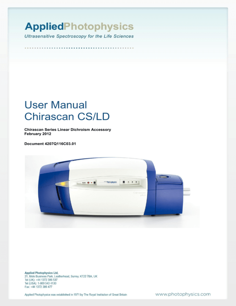
User Manual
Chirascan CS/LD
Chirascan Series Linear Dichroism Accessory
February 2012
Document 4207Q116C03.01
CS/LD Accessory User Manual
This page is intentionally left blank
Document 4207Q116C03.01
Page 2 of 12
CS/LD Accessory User Manual
This document contains important safety information. Read this document and the
Chirascan series User Manual before attempting to install or use the CS/LD
accessory. Failure to do so could result in death or serious injury.
Document 4207Q116C03.01
Page 3 of 12
CS/LD Accessory User Manual
USE OF THIS DOCUMENT
This document is intended to inform the operator of Applied Photophysics’ CS/LD linear dichroism accessory on
its design, installation and operation. The CS/LD is used with either the Chirascan or Chirascan-plus
spectrometer and this document should be used in conjunction with the User Manual applicable those
instruments. It is assumed that the user of this document is familiar with the operation of the Chirascan or
Chirascan-plus, and with Applied Photophysics Pro-Data software. In particular it is assumed that the user is
familiar with the hazards associated with the operation of the spectrometer, and has read the safety information
contained in its User Manual.
The information in this document is subject to change without notice and should not be construed as a
commitment by Applied Photophysics, who accept no responsibility for errors that may appear herein. This
document is believed to be complete and accurate at the time of publication, and in no event shall Applied
Photophysics be held responsible for incidental or consequential damages with or arising from the use of this
document.
COPYRIGHT 2012 APPLIED PHOTOPHYSICS LTD. ALL RIGHTS RESERVED. THIS DOCUMENT OR
PARTS THEREOF SHALL NOT BE REPRODUCED IN ANY FORM WITHOUT THE WRITTEN PERMISSION
OF THE PUBLISHER.
THE SOFTWARE PROVIDED WITH THE CHIRASCAN AND ITS ACCESSORIES (PRO-DATA CHIRASCAN,
PRO-DATA VIEWER, ETC.) IS THE PROPERTY OF APPLIED PHOTOPHYSICS LTD. (“APL”) AND IS
SUPPLIED UNDER LICENCE. APL IS WILLING TO LICENSE THE SOFTWARE ONLY UPON THE
CONDITION THAT THE LICENSEE ACCEPTS ALL THE TERMS CONTAINED IN THE LICENCE
AGREEMENT. THESE INCLUDE THAT THE LICENSEE MAY NOT SELL, RENT, LOAN OR OTHERWISE
ENCUMBER OR TRANSFER LICENSED SOFTWARE IN WHOLE OR IN PART TO ANY THIRD PARTY. FOR
A FULL COPY OF THE LICENCE PLEASE CONTACT APL OR SEE THE SOFTWARE INSTALLATION DISC.
Chirascan™ and Chirascan™-plus are trademarks of Applied Photophysics Ltd.
Microsoft® and Windows® are registered trademarks of Microsoft Corporation in the United States and other
countries.
All other trademarks or registered trademarks are the sole property of their respective owners.
Document 4207Q116C03.01
Page 4 of 12
CS/LD Accessory User Manual
HAZARD AND OTHER INDICATORS
HAZARD INDICATORS USED IN THIS DOCUMENT
The sign to the left is used to indicate a hazardous situation, which, if not avoided, could result in
death or serious injury.
OTHER INFORMATORY INDICATORS USED IN THIS DOCUMENT
The sign to the left is used to indicate a situation which, if not avoided, could result in damage to
the instrument.
Document 4207Q116C03.01
Page 5 of 12
CS/LD Accessory User Manual
ESSENTIAL SAFETY INFORMATION
MAKE SURE THAT YOU HAVE READ AND UNDERSTAND ALL THE SAFETY INFORMATION CONTAINED
IN THIS DOCUMENT BEFORE ATTEMPTING TO INSTALL OR OPERATE THE LINEAR DICHROISM
ACCESSORY. IF YOU HAVE ANY QUESTIONS REGARDING THE OPERATION OF THE ACCESSORY,
PLEASE CONTACT APL TECHNICAL SUPPORT SECTION AT THE ADDRESS SHOWN ON THE FIRST
PAGE OF THIS DOCUMENT.
OBSERVE ALL SAFETY LABELS AND NEVER ERASE OR REMOVE SAFETY LABELS.
PERFORMANCE OF INSTALLATION, OPERATION OR MAINTENANCE PROCEDURES OTHER THAN
THOSE DESCRIBED IN THIS USER MANUAL MAY RESULT IN A HAZARDOUS SITUATION AND WILL VOID
THE MANUFACTURERS WARRANTY.
The Chirascan spectrometer is powered by the mains electricity supply which can produce a
shock leading to serious injury or death. Do not connect or disconnect the instrument from the
mains supply unless the supply is powered off at source. Ensure all communications and
electrical connections are made before powering on the spectrometer. Exercise care during
operation and do not operate units with their covers removed. Operate the spectrometer using
only the cables provided. Never operate a spectrometer with damaged cables.
The Linear Dichroism photomultiplier tube (PMT) and Large Area Photodiode (LAAPD)
detectors operate at high voltages can produce a shock leading to serious injury or death. Do not
connect or disconnect the detector from the spectrometer unless the spectrometer is powered
off.
Document 4207Q116C03.01
Page 6 of 12
CS/LD Accessory User Manual
CS/LD INSTALLATION AND OPERATIONAL REQUIREMENTS
Environmental and electrical requirements
The CS/LD has no environmental requirements additional to those of the Chirascan or Chirascan-plus
spectrometer. Operation of the CS/LD is controlled by the Chirascan electronics, and there are no additional
electrical requirements.
Bench space
The CS/LD has no bench space requirements additional to those of the Chirascan spectrometer, although some
users may choose to use an external device to generate flow in the LD, which may add to the bench space
requirement.
Nitrogen purge gas
The CS/LD has no purge gas requirements additional to those of the Chirascan spectrometer.
Servicing
Servicing of the CS/LD should only be undertaken by qualified personnel. If you are in any doubt at all please
contact the Applied Photophysics Technical Support Department at the address given on the front of this User
Manual.
Document 4207Q116C03.01
Page 7 of 12
CS/LD Accessory User Manual
GLOSSARY
The following abbreviations may be found in this User Manual
APL
CD
LD
PMT
Applied Photophysics Ltd.
Circular dichroism
Linear dichroism
Photomultiplier tube
HYPERLINKS
This document contains hyperlinks between references (for example the Contents tables, or references to
Sections or Figures in the text), and sources. To follow a link, place the cursor over the reference and use
CTRL+click. Hyperlinks in the text are indicated by underlined blue font.
.
Document 4207Q116C03.01
Page 8 of 12
CS/LD Accessory User Manual
CONTENTS
USE OF THIS DOCUMENT....................................................................................................................................... 4
HAZARD AND OTHER INDICATORS ....................................................................................................................... 5
ESSENTIAL SAFETY INFORMATION ...................................................................................................................... 6
CS/LD INSTALLATION AND OPERATIONAL REQUIREMENTS ............................................................................ 7
GLOSSARY ............................................................................................................................................................... 8
CONTENTS ............................................................................................................................................................... 9
FIGURES ................................................................................................................................................................... 9
1 INTRODUCTION .................................................................................................................................................. 10
2 INSTALLATION AND OPERATION ..................................................................................................................... 11
2.1 Hardware installation .................................................................................................................................. 11
2.2 Configuration and calibration ..................................................................................................................... 11
2.3 Operation.................................................................................................................................................... 11
FIGURES
Figure 1.1: flow cell of the type commonly used with the CS/LD ............................................................................ 10
Figure 2.1: the Signal panel .................................................................................................................................... 11
Figure 2.2: LD spectra for calf thymus DNA at three different flow rates ............................................................... 12
Document 4207Q116C03.01
Page 9 of 12
CS/LD Accessory User Manual
1 INTRODUCTION
Linear dichroism is the difference in the absorbance of parallel and perpendicular linearly polarized light
(Equation 1.1). It is usually produced by preferential orientation of macromolecules, for example by stretching
along the streamlines in a flow field.
A = A|| - A
1.1
where A is the absorbance of the linearly polarised light, and the subscripts || and indicate parallel and
perpendicular respectively.
On older Chirascan and Chirascan-plus spectrometers, linear dichroism measurements required a different
detector from that used for circular dichroism measurements. On current instruments (April 2011 onwards), the
same detector may be used for both, although it needs to be configured and calibrated for each mode. This
should be done by a qualified APL engineer.
Figure 1.1: flow cell of the type commonly used with the CS/LD
Sampling handling and orientation are left to the discretion of the user. Commonly a flow through cell such as
that shown in Figure 1.1, available from Hellma UK Ltd., is used. The use of a concentric cylinder (Couette) type
flow cell is also well established.
For more information on linear dichroism and its measurement, see B. Norden, A. Rodger and T. Dafforn “Linear
Dichroism and Circular Dichroism”, RSC Publishing, 2010
Document 4207Q116C03.01
Page 10 of 12
CS/LD Accessory User Manual
2 INSTALLATION AND OPERATION
2.1 Hardware installation
The Linear Dichroism photomultiplier tube (PMT) and Large Area Photoediode (LAAPD) detector
operate at high voltages can produce a shock leading to serious injury or death. Do not connect
or disconnect the detector from the spectrometer unless the spectrometer is powered off.
The detectors currently (April 2011 onwards) supplied with the Chirascan or Chirascan-plus spectrometers can
also be used in CD mode, and their installation is described in the main Chirascan User Manual.
2.2 Configuration and calibration
The detector needs to configured and calibrated for LD measurements. If the LD option was purchased with the
spectrometer, this will have been performed by APL as part of the production process. If the LD option is
purchased as an upgrade, then the configuration and calibration will need to be performed by an APL qualified
engineer.
Incorrect configuration of the detector can cause damage to the instrument or give incorrect
results, and LD calibration of the detector requires a special rig. Configuration and calibration
should only be performed by a qualified APL engineer.
Note that the calibration factors are specific to a particular detector. Users upgrading from a single mode CD
detector should not use the single mode CD detector and the CD/LD detectors interchangeably.
2.3 Operation
From the drop-down list on the Signal panel on the Chirascan Pro-Data control page, select Linear Dichroism
(Figure 2.1). From then on, operation of the instrument is similar to that when making CD measurements, for
details of which see the main Chirascan series User Manual.
Figure 2.1: the Signal panel
Document 4207Q116C03.01
Page 11 of 12
CS/LD Accessory User Manual
Typically, when making LD measurements, a baseline is taken with no sample present, and LD spectra are then
measured with the sample present but no flow, and then at selected flow rates. Background correction is made
by subtracting the spectrum measured without flow from those measured with flow.
Figure 2.2: LD spectra for calf thymus DNA at three different flow rates
Results for calf thymus DNA at a concentration of 1 mg/ml in phosphate buffered saline are shown in Figure 2.2
at three different pump speeds: 30 ml/min, (orange), 15 ml min (red), and 7.5 ml min (cyan). A 0.5 mm
pathlength x 4 mm width flow cell of the type shown in Figure 1.1 was used, with an RH00CTC pump supplied by
Fluid-Metering Inc. Syosset, NY, USA .
The spectra have been corrected for background (spectrum with the pump turned off) and a 3-point smooth has
been applied to even out the effect of the pulsing pump motion.
Document 4207Q116C03.01
Page 12 of 12


