DATE
NOTES
PROJECT
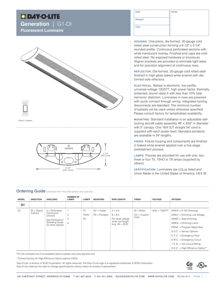
Generation | G1-DI
TYPE
Fluorescent Luminaire
HOUSING :
One-piece, die-formed, 20-gauge cold
rolled steel construction forming a 9 1/2" x 3 1/4"
rounded profile. Continuous perforated sections with
white translucent overlay. Finished end caps are cold
rolled steel. No exposed hardware or knockouts.
Aligner brackets are provided to eliminate light leaks
and for precision alignment of continuous rows.
REFLECTOR :
Die-formed, 20-gauge cold rolled steel
finished in high gloss baked white enamel with dieformed side reflectors.
MOU N T I NG O P T I O NS
D I S TRI B UTION
ELECTRICAL : Ballast is electronic, low profile,
universal voltage 120/277, high power factor, thermally
protected, sound rated A with less than 10% total
harmonic distortion. Luminaires in rows are prewired
with quick connect through wiring. Integrated locking
disconnects are standard. The minimum number
of ballasts will be used unless otherwise specified.
Please consult factory for lamp/ballast availability.
MOUNTING :
Standard installation is an adjustable selflocking aircraft cable assembly 48" x 3/32" in diameter
with 5" canopy. One 16/4 SJT straight 54" cord is
supplied with each power feed. Standard pendants
are available in 24" lengths.
Y Cable
Direct / Indirect
Wall
Direct / Indirect
Suspended
Cable
Stem
FINISH :
Fixture housing and components are finished
in baked white enamel applied over a five-stage
pretreatment process.
3 1/4"
[82.5 mm]
LAMPS :
Fixtures are provided for use with one, two,
three or four T5, T5HO or T8 lamps (supplied by
others).
9 1/2"
[241.3 mm]
CERTIFICATION :
Luminaires are cULus listed and
Union Made in the United States of America. I.B.E.W.
Ordering Guide (choose from the lists below and specify)
MODEL
DIRECTION
SHIELDING
DI = Direct/
Indirect
3 = Perforated
Continuous
(shown)
NUMBER OF
LAMPS
LAMPS
MOUNTING
ROW LENGTH
FINISH
VOLTAGE
OPTIONS*
1
T5
AC = Cable
4 = 4 ft
W = White
UNV = 120/277
DIM10 = 0-10V Dimming
2
T5HO
PD = Pendant
8 = 8 ft
3
T8
CC = Custom
Color
G1
G1
See Perforation/
Shielding Guide
for other options.
For other, please
enter row length
(e.g. 48 = 48 ft)
4
DIMLV = Dimming Line Voltage
DIMST = Step Dimming
DIMHL = Dimming Lutron
PRGS = Program Rapid Start
S O C = Sensor Options
E P C = Emergency Pack
E M C = Emergency Circuit
T C W = Two Circuit Wiring
H E O = High Efficiency Optics**
*For the complete list of all available options please visit www.dayolite.com
**Consult factory for High Efficiency Optics options (HEO).
Day-O-Lite, a division of SCW Corporation. All rights reserved. The Day-O-Lite logo is a registered trademark of SCW Corporation.
Day-O-Lite reserves the right to change specifications without notice for product improvement.
126 CHESTNUT STREET, WARWICK RI 02888
T 401.467.8232
F 401.941.2960
SALES@DAYOLITE.COM
WWW.DAYOLITE.COM
REV081813
PAGE 1
Generation | G1-DI
Linear Sections and Suspension Location
11'-10 1/2" O.C.
3/4"
3/4"
7'-10 1/2" O.C.
3/4"
12' O.A.L.
3/4"
3/4"
3'-10 1/2 O.C.
3/4"
3/4"
4' O.A.L.
8' O.A.L.
3/4"
11'-10 1/2" O.C.
8' O.C.
8' O.C.
4' O.C.
12' EL (End Left)
8' MR (Middle Row)
8' MR (Middle Row)
4' ER
(End Right)
32' O.A.L. of Run
Installation Preparation
End Cap
Alignment
Tear-Out
Fixtures in rows are joined with
supplied harware as shown.
Standard installation is an
adjustable self-locking aircraft
cable assembly 48" x 3/32" in
diameter with 5" canopy. One
16/4 SJT straight 54" cord is
supplied with each power feed.
Standard pendants are available
in 24" lengths.
(2) 1/4 20
Hex Nut
(2) 1/4 20
Hex Bolt
Housing Alignment
Bracket
Photometry
COEFFICIENTS OF UTILIZATION–ZONAL CAVITY METHOD
CANDELA DISTRIBUTION
pfc = 0.20
Vert.
Angle
0
22.5
45
67.5
90
0
10
20
30
40
50
60
70
80
90
100
110
120
130
140
150
160
170
180
84
75
74
63
54
48
37
25
18
11
181
398
625
839
1007
1147
1252
1302
1325
84
75
70
64
55
45
36
26
14
19
289
529
723
909
1066
1194
1285
1317
1325
84
74
69
64
55
45
36
27
14
24
371
663
850
981
1124
1230
1303
1317
1325
84
74
69
64
56
47
36
26
17
24
419
717
949
1046
1168
1267
1311
1329
1325
84
76
69
64
54
45
35
24
19
24
423
734
983
1080
1169
1276
1318
1344
1325
pcc
pw
.7
.5
RCR
0
1
2
3
4
5
6
7
8
9
10
85
77
70
64
58
53
49
45
41
38
36
85
74
64
56
49
44
39
35
31
28
26
.8
.3
.1
.7
.5
85
70
59
50
43
37
32
28
25
22
20
85
66
53
43
36
30
26
22
19
16
14
73
66
60
55
50
46
42
38
35
33
31
73
63
55
49
43
38
34
30
27
25
22
.7
.3
.1
.5
.5
.3
73
61
51
44
38
32
28
25
22
19
17
73
57
46
38
32
27
23
19
17
15
13
51
44
39
34
30
27
24
21
19
18
16
51
43
36
31
27
23
20
18
16
14
13
.1
51
41
33
27
23
19
17
14
12
11
9
.5
.3
.3
.1
.1
0
0
31
27
24
21
18
16
15
13
12
11
10
31
26
22
19
17
14
13
11
10
9
8
31 13 13 13
25 10 10 10
21 9 9 9
17 7 7 7
14 6 6 6
12 5 5 5
10 4 4 4
9 4 4 4
8 3 3 3
7 3 3 3
6 3 3 3
4
3
3
2
2
2
1
1
1
1
1
.5
.1
.3
G1-DI-3-2T8 (HEO)**
Total Luminaire Optical
Efficiency = 87.9%
**Consult factory for High Efficiency Optics options (HEO).
180°
225°
135°
270°
90°
315°
45°
0°
0
45
90
Lamp (2) 32w T8
Lumens: 2900 Per Lamp
Optical Distribution:
5% Direct: 95% Indirect
126 CHESTNUT STREET, WARWICK RI 02888
T 401.467.8232
F 401.941.2960
SALES@DAYOLITE.COM
WWW.DAYOLITE.COM
REV081813
PAGE 2

