s6 battery replacement - Finish Thompson, Inc.
advertisement

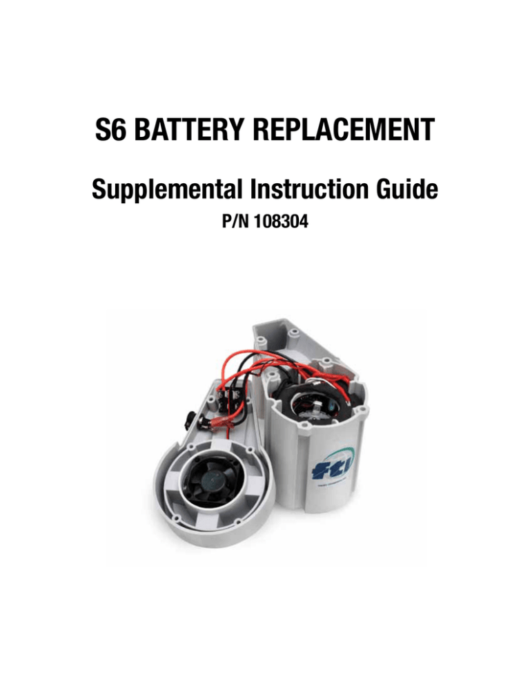
S6 BATTERY REPLACEMENT Supplemental Instruction Guide P/N 108304 Battery Pack Removal Tools Required: S6 Operation & Parts Manual, Phillips Head Screwdriver, Needle Nose Pliers, Wire Stripping / Crimping Tool, & Electrical Tape. 1. Verify motor switch is in the OFF position “O” on the switch before beginning. 2. Remove the 6-high-low screws (item 5) from the motor cover (item 1) & lift off. See Figure 1. 3. Remove red & black motor lead wires from the motor terminals one at a time. See Figure 2. Warning: To prevent a short circuit & battery overheating if lead wires touch, tape over the terminals with electrical tape immediately upon removal. 4. Pull the battery pack (item 2) from the motor canister (item 4) using 2 fingers inserted into the middle of the battery pack. See Figure 3. Figure 1 Figure 3 Figure 2 5. Pull motor red & black lead wires with thin red & black fan wires from the battery pack side openings. See Figure 4. 6. Cut the thicker red & black motor lead wires one at a time ½” from the battery pack. See Figures 5 & 6. Caution: Do not cut the thin red & black fan wires. Figure 5 Figure 4 Figure 6 7. Strip the Red & Black lead wires ¼” from the cut end. See Figure 7. 8. Set the new replacement battery pack next to the old battery pack. Begin transferring wires one at a time from the old battery pack to the new one. See Figure 8. Figure 7 Figure 8 9. Start with the black motor lead wire & install it into the blue butt connector installed on the thick black wire from the battery pack and crimp. Do the same with the Red motor lead wire. See Figures 9 & 10. Note: Make sure the thin red & black fan wires are still wrapped around the lead wires. 10. Swap out the old charging jack wires with the new ones from the replacement battery pack (small straight connectors). Pull off one at a time and make sure to install the new wires in the correct position. See Figure 11. You can pull these off by hand or use a needle nose pliers. Figure 9 Figure 11 Figure 10 11. Swap out the 3 switch wires with insulated flag connectors one at a time. Using a Needle Nose Pliers remove the outside red switch wire first. Replace it with the new red switch wire from the outside of the new battery pack. See Figures 12 & 13. Figure 12 Figure 13 12. Remove the middle red switch wire & replace it with the new red switch wire from the middle of the battery pack. See Figures 14 & 15. Figure 14 Figure 15 13. Remove the last remaining black switch wire & replace it with the new black switch wire from the new battery pack. See Figures 16 & 17. Figure 16 Figure 17 14. Old battery pack should be completely disconnected from the Motor Cover & Fan Assembly. Cut all wires attached to the battery pack one at a time. See figure 18. Old Battery Pack is now ready to be taken to a recycling center. New battery pack is ready to install in motor canister (item 4). To learn more about RBRC, state regulations concerning recycling batteries and battery drop off locations visit their website at www.call2recycle.org or call 1-800-822-8837. (European countries please follow EC Directive Batteries 2006/66/EU.) Figure 18 Battery Pack Installation 1. Route red & black motor leads through the side openings of the new battery pack. See Figures 19 & 20. Figure 20 Figure 19 2. Make sure motor lead wires are not in the battery alignment slots. Slots must be clear in order to slide the battery down properly. See Figure 21. Slide the new battery pack into the motor canister (item 4) with the circuit board facing motor handle. See Figure 22. Illustration shows motor wires in slot. Figure 21 Figure 22 3. Push the battery pack gently down until it bottoms out. Roughly ½” from top of motor canister. See Figure 23. 4. Install the red motor lead wire connector onto the motor terminal marked with a red dot. See Figure 24. 5. Install the black lead wire connector on the other motor terminal. See Figure 25. Figure 23 Figure 24 Figure 25 Testing New Battery Pack 1. Lay motor on its side & turn on the motor switch to low speed “I” on switch. Ensure that both the fan & motor operate properly. Repeat test at high speed “II” on switch. 2. If the motor or the fan does not operate properly check all wire connections. Testing Charger Jack 1. With motor still on its side plug the charger into the charging jack. Charger light should turn red indicating battery is charging. If no light check charging jack connections. Reinstall Motor Cover Assembly 1. Route all wires from the motor canister into the handle area. See figure 26. Tuck the fan and switch wires down into the handle. See Figure 27. Figure 26 Figure 27 2. Close motor cover (item 1) making sure no wires get pinched. Make sure the cover easily fits flush on top of the motor canister. 3. Reinstall the 6 hi-low screws (item 5) while holding the motor cover & canister together. 4. Re-test the motor again at low & high speeds to assure motor is working properly. 5. Retest the charger to make sure battery is charging properly. Part No. 108304, 11-20-12

