EPC-1D Instruction Sheet
advertisement
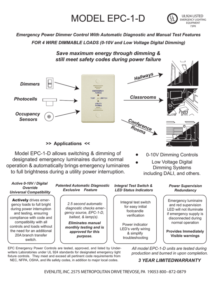
MODEL EPC-1-D UL ® UL924 LISTED EMERGENCY LIGHTING EQUIPMENT 73PK Emergency Power Dimmer Control With Automatic Diagnostic and Manual Test Features FOR 4 WIRE DIMMABLE LOADS (0-10V and Low Voltage Digital Dimming) Save maximum energy through dimming & still meet safety codes during power failure ays w l l a H Dimmers Classrooms Photocells Occupancy Sensors Co nfe Ro rence om s >> Applications << Model EPC-1-D allows switching & dimming of designated emergency luminaires during normal operation & automatically brings emergency luminaires to full brightness during a utility power interruption. Active 0-10V / Digital Override Universal Compatibility Actively drives emergency loads to full bright during power interruption and testing, ensuring compliance with code and compatibility with all controls and loads without the need for an additional 20A branch transfer switch. Patented Automatic Diagnostic Exclusive Feature 0-10V Dimming Controls Low Voltage Digital Dimming Systems including DALI, and others. Integral Test Switch & LED Status Indicators 2.5 second automatic diagnostic checks emer gency source, EPC-1-D, ballast, & lamp(s). Integral test switch for easy initial footcandle verification Eliminates manual monthly testing and is approved for this purpose. Power indicator LED’s verify wiring & simplify troubleshooting EPC Emergency Power Controls are tested, approved, and listed by Underwriters Laboratories under UL 924 standards for designated emergency light fixture controls. They meet and exceed all pertinent code requirements from NEC, NFPA, OSHA, and life safety codes, in addition to major local codes. Power Supervision Redundancy Emergency luminaire and red supervision LED will not illuminate if emergency supply is disconnected during normal operation Provides Immediately Visible warnings All model EPC-1-D units are tested during production and burned in upon completion. 3 YEAR LIMITEDWARRANTY EVENLITE, INC. 2575 METROPOLITAN DRIVE TREVOSE, PA 19053 800--872-0879 Occupancy Sensor Wall Switch or Dimmer Model EPC-1-D Typical Wiring Photocell ZONE CONTROL Regular Neutral Dimmed (+) Load Violet Gray (-) Regular Neutral Dimmed (+) Load Violet Gray (-) Regular Hot Regular Netural Regular Hot Regular Netural 1 or 2 Red Emergency Load Violet(+) Gray(-) Model EPC-1-D 4 EMERGENCY 5 Emergency Neutral REGULAR POWER WIRING Color Connection Black Regular Hot (120V) Orange Regular Hot (277V) Red Switched Hot White Regular Neutral Emergency Dimmed Load POWER TEST Emergency Hot Gray(-) 3 To Additional Regular Loads Violet(+) Gray(-) Cap Off Blue Black Wire # 1 2 3 4 Hot Hot * SwitchedHot Regular Neutral SWITCH UTILITY POWER Violet (+) Gray (-) Hot Neutral Emergency Dimmed Load Violet (+) Gray (-) To Additional Emergency Loads Hot Neutral Emergency Switched Hot Emergency Neutral 6 7 EMERGENCY POWER WIRING Wire # Color Connection 5 Blue Emergency Hot 6 Yellow Emergency Load Hot White/Blue Emergency Neutral Stripe 7 PLENUM CABLE B LOW VOLTAGE WIRING Blue Dimmer Violet(+) Emergency Load Red Violet(+) Black Cap Off Zone Control device can be any combination of the following: * NOTE: a) Intelligent zone controller including both low voltage dimming output & line voltage switching output. b) Line voltage switching devices (such as occupancy sensor contact, time clock, relay panel) & low voltage dimming devices including photocells, wall dimmers, & other low voltage dimming signals (0-10V or digital). See p.4 for alternate wiring diagrams and frequently asked questions Theory of Operation Normal Operation: The zone control device turns on and off both regular and emergency luminaires simultaneously. The zone dimmer control dims regular and emergency luminaires simultaneously. Switched and dimmed control of emergency luminaires is accomplished through Emergency Power Dimmer Control, EPC-1-D. Emergency Operation: Wire input #1 or #2 and neutral are connected internally to a utility power sensing circuit. During a utility power interruption, the EPC-1-D energizes wire #6, which switches on emergency load(s) regardless of switch position. Additionally, the low voltage dimming circuit is disconnected from the emergency load(s), which are then brought to full brightness (100%), regardless of dimmer position. Automatic Diagnostic & Testing Operation: When the zone control is turned off, such as at the end of the day, the emergency luminaires stay on at full brightness for 2.5 seconds & indicate that an emergency power source was available & that the EPC-1-D, ballast, & lamp(s) are all functioning correctly. This satisfies the monthly test requirement required by law. When extended duration testing is desired, such as during initial start-up foot candle readings, the manual test button can be pressed. Emergency Power Clarification: Emergency Line power is supplied at all times from a 24 hour emergency power panel. During normal time this panel is suppled with utility power. During a utility power failure, it is supplied with generator or equivalent power. 2 Mounting Electrical Specifications Dual Voltage: 120V/277V Sensing Input , 120V/277V Load 20 Amp Ballast Load Rating 1800W Incandescent Load Rating at 120V 1500W Incandescent Load Rating at 277V Voltage Surge Protection UL924 Listed Can be mounted flush or above the suspended ceiling * Accessibility requiements limit the mounting of emergency controls to accessible areas for testing reasons, however the EPC-1-D automatic diagnostic exempts it from these requirements. Mechanical Specifications Shipping Weight: 8 oz | Color : White Temperature: 32˚F - 140˚F Flush Mounted Size: 4-3/4” x 2-3/4” x 1/4” Body Size: 2-7/8” x 1-3/4” x 1-3/4 UL94-5VA Rating: Safe for installation above the suspended ceiling. Initial Testing, Troubleshooting & Maintenance of EPC-1-D In a new installation, where 10 or 100 separate devices may be used, each having as many as 14 wires to be correctly connected, it is important that a fast convenient method is used to check the connections. In order to test that the wires are connected correctly, without any inconvenience to other occupants, do not turn off regular utility supplied power or turn on the emergency generator until you have checked each EPC-1-D device and light fixtures using the following methods. When room switch is on & dimmer is at full-bright setting, emergency & regular fixtures should be illuminated at full-bright. 1) To test normal operation, ensure branch circuit breaker is connected and utility power is available. If green LED is not illuminated, confirm wiring connections and continuity to branch panels. 2) To test emergency operation, ensure emergency source is connected and red LED is illuminated. Turn room switch to “OFF” position, and ensure that emergency lights stay illuminated for at least 2.5 seconds. If emergency lights do not stay on for at least 2.5 seconds, confirm wiring connections and continuity to emergency panel and emergency power source. No maintenance is required to keep the EPC-1-D functional. However, regular testing should be performed when the lamps or ballasts have been replaced or when facility remodeling has taken place. Single Line Drawings 20A NORMAL POWER PANEL ZONE CONTROLLER Photocell Regular Utility Power Emergency UL 1008 Power Source Transfer Switch Neutral Or Equivalent Not Shown UL 924 EPC-1-D CONTROL REGULAR ROOM LIGHTS DESIGNATED EMERGENCY LIGHTS SD 20A EMERGENCY POWER PANEL EPC-1-D EPC-1-D CONTROL EPC-1-D CONTROL 3 Frequently Asked Questions Question: What if there is only 1 light fixture in the room? What if all light fixtures are emergency fixtures? Answer: Follow the standard wiring diagram on p.2. Treat the fixture(s) as “emergency dimmed loads” & follow standard wiring diagram on p.2. “Regular dimmed load” is not used in this application. Question: What if using a digital low voltage dimmer control & ballasts, such as DALI protocol? Answer: Follow the standard wiring diagram on p.2. Violet and Gray leads will be designated as “D1,D2” Occupancy Photocell or equivalent for digital low voltage signal. If no line voltage Sensorswitch is used, see Alternate Wiring C, below. Special Applications/Alternate Wiring for EPC-1-D ZONE The wide range of 0-10V controls and loads available has led to aCONTROL number of Wall Switch or Dimmer different requirements and standards. The EPC-1-D is designed to accomodate many alternate or special applications, and to ensure proper operation for all ballast or controller manufacturers. If the application required is not listed below, Regular Hot contact LVS, Inc. at 1-800-982-4587 for a custom wiring diagram. Regular Netural When grounding of the low voltage input of a ballast is required during Occupancy emergency operation: Photocell Sensor Use Alternate Diagram “A.” Plenum Cable B Black to ground, all line voltage leads are identical. A Hot Regular Neutral Alternate Dimmed Wiring Diagram “A”(+) Load Violet Gray (-) Blue Black 3 Regular Hot 1 or 2 ZONE Netural 4 When a minimum resistive load is required on theRegular low voltage input of a B CONTROL ballast during emergency operation: Wall Switch or Dimmer Use Alternate Diagram “B.” Connect a resistor (minimum resistance 75KΩ) between Plenum Cable B black lead and gray input of emergency ballasts, all Emergency Hot line voltage leads are identical. C Occupancy Sensor Wall Switch or Dimmer Photocell EMERGENCY POWER Dimmed UTILITY Diagram “B” (+) POWER Violet Load Gray (-) Blue Black 3 1 or 2 Hot Regular Neutral Dimmed (+) Load Violet Gray (-) Regular Hot Regular Netural 4 3 1 or 2 4 5 7 5 To Additional 7 Emergency Dimmed Load SWITCH Regular Hot (unswitched) UTILITY POWER Neutral 6 Regular Loads Violet(+) Gray(-) Red Emergency Load Violet(+) Gray(-) Model EPC-1-D EMERGENCY POWER TEST Red EMERGENCY POWER TEST Gray(-) Cap Off Emergency Hot Emergency Neutral Dimmed (+) Load Violet Gray (-) Cap Off Blue Black Regular Hot Regular Netural Emergency Hot Hot Regular Neutral Emergency Neutral 6 Model EPC-1-D Alternate Wiring Diagram “C” ZONE CONTROL Emergency Hot Dimmed TEST SWITCH Regular Neutral Load Alternate Wiring Ω min. switching: Use Alternate Diagram “C.” Please note that for this application the automatic diagnostic feature does not function, therefore manual monthly testing is required by NEC. Regular Hot Regular Netural Model EPC-1-D 5 7 Regular Hot Neutral Emergency Regular Netural When using a digital low voltage dimmer control with no line voltage Red Emergency Dimmed Load SWITCH UTILITY POWER 6 Cap Off Violet (+) Gray (-) Hot Neutral Emergency Dimmed Load Violet (+) Gray (-) Hot Neutral To Additional Emergency Loads Emergency Hot Emergency Neutral
