Related course notes
advertisement

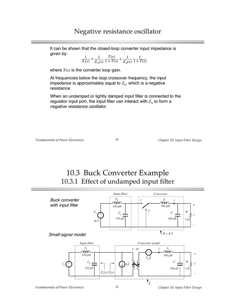
It can be shown that the closed-loop converter input impedance is given by: T(s) 1 = 1 1 + 1 Z i(s) Z N (s) 1 + T(s) Z D(s) 1 + T(s) where T(s) is the converter loop gain. At frequencies below the loop crossover frequency, the input impedance is approximately equal to ZN, which is a negative resistance. When an undamped or lightly damped input filter is connected to the regulator input port, the input filter can interact with ZN to form a negative resistance oscillator. Input filter Lf Buck converter with input filter Converter L 1 330 μH Vg + – 30 V i + 100 μH 2 Cf 470 μF C R 100 μF 3Ω v – D = 0.5 Small-signal model Input filter Lf Converter model 1:D + – 330 μH g + – Vg Cf I 470 μF Zo(s) Zi(s) L + 100 μH C R 100 μF 3Ω – L 1:D + Z D(s) = 12 sL + R || 1 sC D C R ZD(s) – 40 dBΩ 30 dBΩ 1 2π LC 1.59 kHz 1 2πRC 530 Hz fo = f1 = R = 12 Ω D2 ωL D2 || ZD || || ZN || 20 dBΩ 1 ωD 2C 10 dBΩ R0 /D 2 C = fo = 3 → 9.5 dB L f1 Q=R 0 dBΩ 100 Hz 1 kHz 10 kHz f test(s) test(s) 0 1:D 0 test + – Z N (s) = + test Vg ZN(s) L + + s 0 I C – – R 0 – Hence, Solution: test(s) = I (s) – Z N (s) = Vg (s) test(s) = – D Vg (s) D I(s) = – R2 D 40 dBΩ Qf → ∞ 30 dBΩ Lf 20 dBΩ Cf || Zo || 10 dBΩ Zo(s) 0 dBΩ Z o(s) = sL f || 1 sC f R0 f = ωL f – 10 dBΩ ff = – 20 dBΩ Lf = 0.84 Ω Cf 1 = 400 Hz 2π L f C f 100 Hz 1 ωC f 1 kHz f No resistance, hence poles are undamped (infinite Q-factor). In practice, losses limit Q-factor; nonetheless, Qf may be very large. Z o Z N , and Zo ZD 40 dBΩ Qf → ∞ 30 dBΩ f1 = 530 Hz fo = 1.59 kHz 12 Ω ωL D2 || ZN || 20 dBΩ 10 dBΩ || Zo || 1 ωD 2C 0 dBΩ – 10 dBΩ || ZD || R0 /D 2 Q=3 R0f ωL f 1 ωC f ff = 400 Hz – 20 dBΩ 100 Hz 1 kHz 10 kHz f Can meet inequalities everywhere except at resonant frequency ff. Need to damp input filter! Z 1+ o ZN Z 1+ o ZD 10 dB 0 dB – 10 dB 0˚ Zo ZN – 180˚ ∠ Z 1+ o ZD 1+ – 360˚ 10 kHz 1 kHz 100 Hz f || Gvd || 40 dB 30 dB ∠ Gvd || Gvd || Dashed lines: no input filter 20 dB 10 dB 0 dB ∠ Gvd 0˚ – 10 dB Solid lines: including effect of input filter – 180˚ – 360˚ 100 Hz – 540˚ 10 kHz 1 kHz f Undamped filter: Two possible approaches: Lf Lf Cf Cf Rf Zo(s) Rf Lf Cf To meet the requirement Rf || ZN ||: Lf R f R2 D Cf Rf The power loss in Rf is Vg2/ Rf, which is larger than the load power! Lf A solution: add dc blocking capacitor Cb. Rf Cf Choose Cb so that its impedance is sufficiently smaller than Rf at the filter resonant frequency. Cb || Zo ||, with large Cb Lf Rf Rf R0f Cf ωL f Cb ff 1 ωC f 40 dBΩ f1 = 530 Hz 30 dBΩ fo = 1.59 kHz 12 Ω ωL D2 || ZN || 20 dBΩ 1 ωD 2C 10 dBΩ – 10 dBΩ R0 /D 2 Q=3 || Zo || Rf = 1 Ω 0 dBΩ ωL f – 20 dBΩ 100 Hz || ZD || R0f 1 ωC f ff = 400 Hz 1 kHz 10 kHz f || Gvd || 40 dB 30 dB ∠ Gvd || Gvd || Dashed lines: no input filter 20 dB 10 dB 0 dB ∠ Gvd 0˚ Solid lines: including effect of input filter – 10 dB – 90˚ – 180˚ 10 kHz 1 kHz 100 Hz f Simulation of control-to-output responses Undamped vs. damped input filters Plotting the filter output impedances Simulink files for previous slide ! ! ! ! ! ! ! ! ! !" ! ! #" ! Resulting control-to-output transfer function Rf –Cb Parallel Damping Rf –Lb Series Damping Lf v1 + Lb v2 Rf Rf + – Cf Cb v1 – + – Lf + Cf v2 – Rf –Lb Parallel Damping Lb Rf Lf v1 + – Cf + • Size of Cb or Lb can become very large v2 • Need to optimize design –

