knowledge based interpretation of line drawing images
advertisement

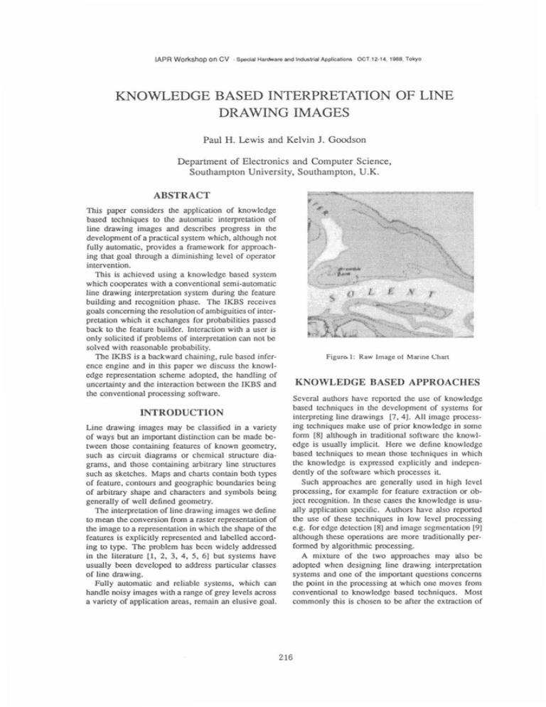
lAPR Workshop on CV - Special Hardrware and Industrial Applications OCT.12-14. 1988, Tokyo KNOWLEDGE BASED INTERPRETATION OF LINE DRAWING IMAGES Paul H. Lewis and Kelvin J. Goodson Department of Electronics and Computer Science, Southampton University, Southampton, U.K. ABSTRACT This paper considers the application of knowledge based techniques to the automatic interpretation of line drawing images and describes progress in the development of a practical system which, although not fully automatic, provides a framework for approaching that goal through a diminishing level of operator intervention. This is achieved using a knowledge bascd system which cooperates with a conventional semi-automatic line drawing interpretation system during the feature building and recognition phase. The IKBS receives goals concerning the resolution of ambiguities of interpretation which it exchanges for probabilities passed back to the feature builder. Interaction with a user is only solicited if problems of interpretation can not be solved with reasonable probability. The IKBS is a backward chaining, rule based inference engine and in this paper we discuss the knowledge representation scheme adopted, the handling of uncertainty and the interaction between the IKBS and the conventional processing software. INTRODUCTION Line drawing images may be classified in a variety of ways but an important distinction can be made between those containing features of known geometry, such as circuit diagrams or chemical structure diagrams, and those containing arbitrary line structures such as sketches. Maps and charts contain both types of feature, contours and geographic boundaries being of arbitrary shape and characters and symbols being generally of well defined geometry. The interpretation of line drawing images we define to mean the conversion from a raster representation of the image to a representation in which the shape of the features is explicitly represented and labelled according to type. The problem has been widely addressed in the literature [I, 2, 3, 4, 5, 61 but systems have usually been developed to address particular classes of line drawing. Fully automatic and reliable systems, which can handle noisy images with a range of grey levels across a variety of application areas, remain an elusive goal. Figure 1: Raw Image of Marine Chart KNOWLEDGE BASED APPROACHES Several authors have reported the use of knowledge based techniques in the development of systems for interpreting line drawings [7, 41. All image processing techniques make use of prior knowledge in some form [8] although in traditional software the knowledge is usually implicit. Here we define knowledge based techniques to mean those techniques in which the knowledge is expressed explicitly and independently of the software which processes it. Such approaches are generally used in high level processing, for example for feature exlraction or object recognition. In these cases the knowledge is usually application specific. Authors have also reported the use of these techniques in low level processing e.g. for edge detection [8] and image segmentation [9] although these operations are more traditionally performed by algorithmic processing. A mixture of the two approaches may also be adopted when designing line drawing interpretation systems and one of the important questions concerns the point in the processing at which one moves from conventional to knowledge based techniques. Most commonly this is chosen to be after the extraction of IAPR Mlnrkchnn nn P\l .s ~ ~u..A i u...~ line segments, a process which can be independent of the application specific knowledge. The knowledge processing approach is then used to apply application based knowledge to the task of constructing and identifying items of inlenst in the image. A conventional algorithmic approach to map interpretation is described by Amin and Kasturi [S].They present a map recognition system which can only handle simple binary maps and which is query driven so that only the section of the map image relevant to the query is analysed. Suzuki, Kosugi and Hoshino [2] describe a more sophisticated system for automatic recognition of large scale maps. Rules are presented for controlling the recognition of components on the basis of their geometric structure. High level knowledge may be made explicit in a variety of ways although production rules appear to be the favourite. Their use has been applied to a wide range of image types, particularly for identifying line based structures [ l o ] . Okazaki and Tsuji [7] describe a scheme for interpreting chemical structure diagrams using rules to describe hierarchically the structures of classes of patterns to be identified. Their procedure is initially data driven but with restrictions introduced using knowledge of the target drawings. An alternative approach to the representation of high level knowledge is the use of syntactical descriptions. Bjerch and Taxt [ l l ] have adopted this approach for the recognition of numbers and some symbols during map in1crpreta:ion whilst hladcrlechner, Egeli and Klein [4] have used the technique for recognising various types of line structure. The main advantages of the knowledge based approach derive from the simple and direct mapping between the high level knowledge and the way in which it is represented in the software. Also there is a unified approach to processing inherent in the concept of a single inference engine. Disadvantages include the fact that more than one knowledge r e p resentation scheme may be required to accommodate all the high level knowledge involved and there may be a substantial processing overhead from using this approach. A BASIC FEATURE BUILDER In reference [6] we gave a brief overview of a system we are developing for interpreting line drawing images. In the remainder of this paper, after a summary of the conventional parts of the system, we examine in detail the knowledge processing aspects. The initial application area has bcen the extraction of contours and coastlines from hydrographic charts. Important criteria in the original design of the system were that it should 1. be able to handle noisy real images containing grey level information t .rod ~ ~ 7'' I I d ~ ~ ~ ~ ~ t ~~nrT i ~ ti t0 . 4i~ ionn ~ .----. . : ,, ' ' Rule :: Base , . 7nh.n ~ ~ i ~ ~ orn.7 l m m g UI-l*. T m M n g rwp *I* L h1 , - --_-• 1 I I , '* I--------, I I I 1 :I K : I I I I I B S : --_ --'-- Coherent Figure 2: Schematic of the Interpretation System 2. produce useful results in a relatively short development time 3. involve as little operator intervention as possible 4. be a relatively low cost system compared with e.g. methods using laser scanning techniques. Two important stages may be identified in the total process: firstly, extracting the line work in the image and secondly identifying the groupings of line segments composing the required features. The sequence adopted for the line extraction stage is a modified form of that described by Watson et al. [12]. The image is first blurred using a gaussian filter to give all lines a convex profile. A double adaptive threshold is applied to label points on the ridge structures and also any homogeneous non-background regions. Finally the tracker walks along the ridge top producing a file of line fragments coded using the Freeman chain code. Inevitably some line fragmentation occurs in the tracking process and the feature building stage must group line fragments together to recreate continuous lines in the image and also group the lines together and rccognise them as particular features. This stage clearly involves the use of application specific knowledge about the structure of the features and a semi automatic feature extraction facility (SAFE) has been developed which attempts to build features automatically from the line fragment file, but which solicits operator intervention when necessary. During use of the SAFE system, the original raw image is displayed on the screen in a low grey level range and the features are superimposed on the image ~ IAPR Wnrkchnn nn C\I . s-,;,~ u.,~.,~,~ I ~ A , , ~ + . ; - IA~~I:.--.+:A-. nrr q* 4 1 *noo TALI.. separation of the two systcms was an initial design aim to ensure that the IKBS could bc dcvelopcd indcpendently of the algorithmic software comprising the early processing and the SAFE system. In principle at least, the production of the line fragmcnts file using convcntional image processing, constitutes a clear end point to data driven processing, and the IKBS represents an equally clear implementation of high level, and frequently application spccific knowledge, rcpresented explicitly and processed by a scparate inference engine. The IKBS is slructurally quite gcncral. Facts in the knowledge base are clauses expressed in the format: attribute, relation, value, entities, CF Thus the fact that line featurc 7 is known to be a contour with certainty factor 0.8 is exprcssd as: Figure 3: Feature Highlighting During Extraction in a higher grey level so thcy may be chccked by the operator as they emcrge. Whcn necessary, the operator can control manually the feature building, resolving ambiguities prcscntcd as a sct of options on a menu, or correcting errors in the featurc building process using an interactive image editor. This approach to feature extraction is illustrated schematically by the solid boxes in figure 2. A typical raw image is illustrated in figure 1. It is a 128 x 128 detail from a larger image with 64 grey levels and demonstrates the importance of a facility which can accommodate noisy grey scale images. Figure 3 shows the SAFE system in action on the raw image of figure 1. Some of the coastline features have been extracted and are shown highlighted on the raw image. The heuristics which SAFE uses to link fragments together are essentially very simple. With this arrangement, the real knowledge required to resolve ambiguities and identify cohercnt features is provided by the operator. A COOPERATING IKBS In order to apply high level knowledge automatically in the difficult stages of feature building, an intelligent knowledge based systcm (IKBS) has been developed which can cooperate with the SAFE systcm in this task. The IKBS is a rule based system containing rules governing thc linking of line segments in the feature building process. The coopcrating IKBS interacts with the SAFE system through an area of shared memory. This not only contains pointers to the line segment file, the raw image file and the emerging feature file, but also goals are passed through the area from SAFE to the IKBS and corresponding certainty factors (CF) are returned through it to SAFE, giving an indication of the certainties with which goals have been established. The system is illustrated in figure 2 where the coop erating IKBS is shown as the dotted section. The clear featuretype, is, contour, feature'?,0.8 Ccrtainty factors are in the range 1.0 (fact known with absolute certainty) to -1.0 (definitely false) and initial values may bc estimated rigorously from the variability in thc image or crudcly using an approximating tcchniquc. Rules in the IKBS take the gcncral form IFconditions THEN conclusion where thc conditions are a conjunction of clauses in the form shown above and the conclusion is a similarly formatted clause. e.g. the rule IF endsep, islessthan, 10, (lineA,featureB) , ANDendorient,islessthan,l, (lineA,featureB), THENareconnected, is, true, (lineA,featureB),0.8 says that if the end separation of some line A and some feature B is less than 10 units and the relative orientation of their ends is less than 1 radian then the certainty that linc A and fcature B should be conncctcd is 0.8. The rulcs may be supplied to thc IKBS in an English like form almost identical to that shown hcrc and are translated aulomatically into the IKBS to crcate thc rule base. Condition clauses in the rule specification may bc preceded by the word function to indicate that a procedural function is available to dcrive thc fact and an initial estimate of its certainty if one is not already available in the fact list. For example, in the rule above, functions would bc invoked to calculate thc status of the end separation and orientation of the linc fragment and the feature under consideration. Once a fact has been determined it remains in the fact list for the duration of the analysis. However, the certainty factor may change as further rulcs containing the fact clause as a conclusion are evaluated. Uncertainty in the evaluation of goals may thus emerge from two sources. Firstly, thcre is uncertainty associated with the facts which primarily reflects the variability in the image and secondly there is the uncertainty associated with each rule, which reflects the uncertainty about the rule conclusion assuming each of the rulc conditions is known with absolute certainty. During opention of the systcm, if a rulc is fircd, the certainty factor for the conclusion, C F c say, is the product of the certainty factor of the rule and the minimum certainty factor of the preconditions for the rulc. If the conclusion docs not already exist as a fact, it is added to the fact list with a certainty factor, C F C . If it does exist in the fact list, thc pre-existing certainty factor is modified using the new certainty factor C F C . Goals take the form of individual clauses without certainty factor values. For cxample, the goal isconnected, is, true, (feature3, linel9) asks the question 'is fcature 3 connected to line fragment 19?' Such goals are submitted to the IKBS by SAFE where previously operator intervention was required. Thc IKBS responds by estimating and rcturning a certainty factor for the goal using a backward chaining mechanism. The IKBS is thus a goal directed systcm and conflict resolution is resolved by a priori ordering of the rule basc. In order to rcsolvc an ambiguity, for example when trying to dccidc how to cxtcnd a fcature if more than one candidate linc fragment is available, the SAFE systcm would give a goal to the IKBS for each candidate in turn. The ambiguity is resolved if one of the goals has a ccrtainty factor significantly higher than its nearest rival. Although the total system has currently not been extcndcd to capitalise on it, the IKBS has also been designed to process goals in which some entities in the entity list are unspccified. Thus, if the line was unspecified in the example goal above, the question being asked is 'is there a line fragment which should be connected to feature 3?' References 1 R. W. Smith, "Computer processing of linc images: A survey," Pattern Recognition, vol. 20, no. 1, pp. 7-15, 1987. 2 S. Suzuki, M. Kosugi, and T. Hoshino, "Au!omatic linc drawing recognition of large-scale maps," Oprical Engineering, vol. 26, no. 7, pp. 642-649, 1987. 3 H. Bley, "Segmentation and preprocessing of electrical schematics using picture graphs," Comp. Vision, Graphics and Image Proc., vol. 28, pp. 27 1288, 1984. 4 G. Maderlechner, E. Egeli, and F. Klcin, "Model guided interpretation based on structurally related image primatives," in Knowledge-Based Expert Systems in Industry (J. Kriz, ed.), pp. 91-97, Ellis Horwood, 1987. 5 T. J. Amin and R. Kasturi, "Map data processing: Recognition of lines and symbols," Optical Engineering, vol. 26, no. 4, pp. 354-358, 1987. 6 K. J. Goodson and P. H. Lewis, "Feature cxtraction from line drawing images," in Pattern Recognition, 4th International Conference ( J . Kittler, cd.), pp. 216-221, Springer-Verlag. 1988. 7 S.-i. Okazaki and Y. Tsuji, "Knowledge-based approach for adaptive recognition of drawings," in Pattern Recognition, 4th International Con/erence (J. Kittler, ed.j, pp. 333-342, Springer-Verlag, 1988. 8 A. C. Sleigh, "The extraction of boundaries using local measures driven by rules," Pattern recognition letters, vol. 4, no. 4, pp. 247-258, 1986. 9 A. M. Nazif and M. D. Levinc, "Low level image segmentation : An expert systcm," IEEE Transactions on Pattern Analysis and Machine Intelligence, vol. 6, pp. 555-577, September 1984. CONCLUSIONS So far our system has been used effectively for extracting arbitrary line structures (contours and coastlines) but the IKBS will also allow easy implementation of rules for defining the gwmcby of objects in terms of the line segments of which they are composed. In some applications, the use of linc fragments as the intermediate image representation may not be adequate. Alternative intermediate rcprescntations are being investigated, including a graphical representation of all regions found in the image (including line-regions). Objects defined in like manner could then be recogniscd by graph searching and matching. In spite of the processing overheads which are often involved, knowledge based techniques are sccn to offer an elegant way of bringing high level, application specific knowledge to bear on the problem of line drawing image interpretation. 10 S. A. Slansficld, "Angy: A rule-based expert system for automatic segmentation of coronary vessels from digital subtracted angiograms," IEEE Transactions on Pattern Analysis and Machine Intelligence, VOI. 8, pp. 188-199, March 1986. 11 T. Bjerch and T. Taxt, "Syntax analysis in automated digitising of maps," in Pattern Recognition, 4th International Conference (J. Kittlcr, ed.), pp. 222-229, Springer-Verlag. 1988. 12 L. Watson, K. Arvind, R. Ehrich, and R. Haralick, "Extraction of lines and regions from grey tone linc drawing images," Pattern Recognition, vol. 17, no. 5, pp. 493-507, 1984.


