IJIREEICE 13
advertisement
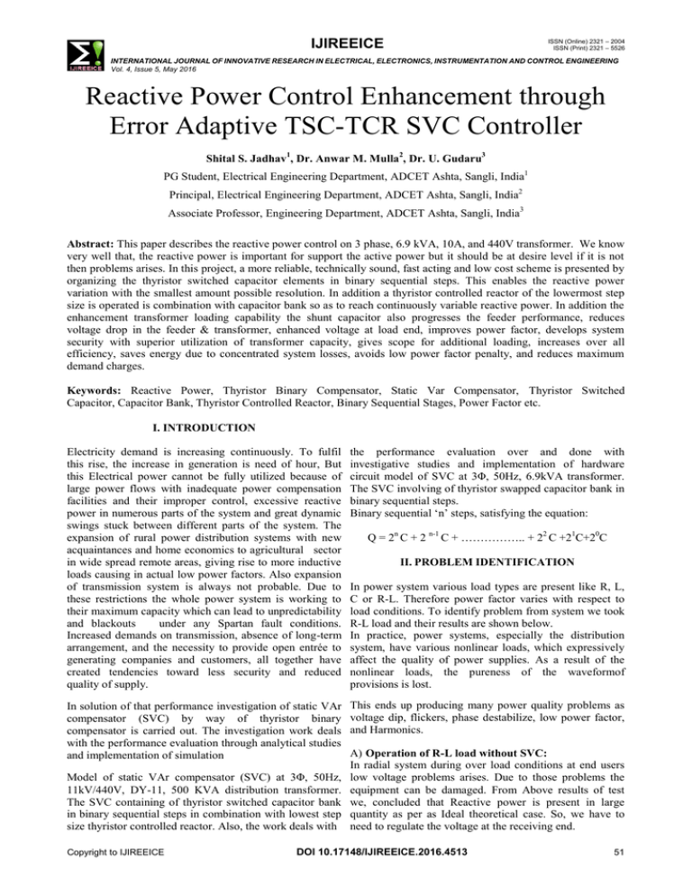
ISSN (Online) 2321 – 2004 ISSN (Print) 2321 – 5526 IJIREEICE INTERNATIONAL JOURNAL OF INNOVATIVE RESEARCH IN ELECTRICAL, ELECTRONICS, INSTRUMENTATION AND CONTROL ENGINEERING Vol. 4, Issue 5, May 2016 Reactive Power Control Enhancement through Error Adaptive TSC-TCR SVC Controller Shital S. Jadhav1, Dr. Anwar M. Mulla2, Dr. U. Gudaru3 PG Student, Electrical Engineering Department, ADCET Ashta, Sangli, India1 Principal, Electrical Engineering Department, ADCET Ashta, Sangli, India2 Associate Professor, Engineering Department, ADCET Ashta, Sangli, India3 Abstract: This paper describes the reactive power control on 3 phase, 6.9 kVA, 10A, and 440V transformer. We know very well that, the reactive power is important for support the active power but it should be at desire level if it is not then problems arises. In this project, a more reliable, technically sound, fast acting and low cost scheme is presented by organizing the thyristor switched capacitor elements in binary sequential steps. This enables the reactive power variation with the smallest amount possible resolution. In addition a thyristor controlled reactor of the lowermost step size is operated is combination with capacitor bank so as to reach continuously variable reactive power. In addition the enhancement transformer loading capability the shunt capacitor also progresses the feeder performance, reduces voltage drop in the feeder & transformer, enhanced voltage at load end, improves power factor, develops system security with superior utilization of transformer capacity, gives scope for additional loading, increases over all efficiency, saves energy due to concentrated system losses, avoids low power factor penalty, and reduces maximum demand charges. Keywords: Reactive Power, Thyristor Binary Compensator, Static Var Compensator, Thyristor Switched Capacitor, Capacitor Bank, Thyristor Controlled Reactor, Binary Sequential Stages, Power Factor etc. I. INTRODUCTION Electricity demand is increasing continuously. To fulfil this rise, the increase in generation is need of hour, But this Electrical power cannot be fully utilized because of large power flows with inadequate power compensation facilities and their improper control, excessive reactive power in numerous parts of the system and great dynamic swings stuck between different parts of the system. The expansion of rural power distribution systems with new acquaintances and home economics to agricultural sector in wide spread remote areas, giving rise to more inductive loads causing in actual low power factors. Also expansion of transmission system is always not probable. Due to these restrictions the whole power system is working to their maximum capacity which can lead to unpredictability and blackouts under any Spartan fault conditions. Increased demands on transmission, absence of long-term arrangement, and the necessity to provide open entrée to generating companies and customers, all together have created tendencies toward less security and reduced quality of supply. the performance evaluation over and done with investigative studies and implementation of hardware circuit model of SVC at 3Φ, 50Hz, 6.9kVA transformer. The SVC involving of thyristor swapped capacitor bank in binary sequential steps. Binary sequential „n‟ steps, satisfying the equation: In solution of that performance investigation of static VAr compensator (SVC) by way of thyristor binary compensator is carried out. The investigation work deals with the performance evaluation through analytical studies and implementation of simulation This ends up producing many power quality problems as voltage dip, flickers, phase destabilize, low power factor, and Harmonics. Model of static VAr compensator (SVC) at 3Φ, 50Hz, 11kV/440V, DY-11, 500 KVA distribution transformer. The SVC containing of thyristor switched capacitor bank in binary sequential steps in combination with lowest step size thyristor controlled reactor. Also, the work deals with Copyright to IJIREEICE Q = 2n C + 2 n-1 C + …………….. + 22 C +21C+20C II. PROBLEM IDENTIFICATION In power system various load types are present like R, L, C or R-L. Therefore power factor varies with respect to load conditions. To identify problem from system we took R-L load and their results are shown below. In practice, power systems, especially the distribution system, have various nonlinear loads, which expressively affect the quality of power supplies. As a result of the nonlinear loads, the pureness of the waveformof provisions is lost. A) Operation of R-L load without SVC: In radial system during over load conditions at end users low voltage problems arises. Due to those problems the equipment can be damaged. From Above results of test we, concluded that Reactive power is present in large quantity as per as Ideal theoretical case. So, we have to need to regulate the voltage at the receiving end. DOI 10.17148/IJIREEICE.2016.4513 51 IJIREEICE ISSN (Online) 2321 – 2004 ISSN (Print) 2321 – 5526 INTERNATIONAL JOURNAL OF INNOVATIVE RESEARCH IN ELECTRICAL, ELECTRONICS, INSTRUMENTATION AND CONTROL ENGINEERING Vol. 4, Issue 5, May 2016 a) The thyristor is fired at the negative/positive peak of voltage, and/or b) Capacitor is pre-charged to the negative/positive peak voltage. The first condition can be met accurately by timing the control circuitry and the second condition is only met immediately after switching off thyristor. The configuration for three capacitor bank steps in binary sequence weight with thyristor switch is shown in Fig.1. Fig.1:- Simplified electrical system of measurement of electrical parameters without SVC B) Test Results: 1 245 1 246 1 235 3.2 245 3. 2 245 3. 2 233 5 245 5 245 5 235 7 245 7 245 7 0.59 (lead) 0.76 (lead) 0.77 (lead) 0.8 (lead) Active power (W) Reactive power (VAR) Ir-phase (Amp) 240 Cosɸ Vr-phase (volts) Vy-phase (volts) Iy- phase (Amp) Vb- phase (volts) Ib- phase (Amp) Table no.1:- Observations under Load Condition 141 .60 571 .52 897 .05 131 6 192. 00 481. 28 733. 95 970. 55 Fig.2:- Thyristor Binary Compensation (TBC) At the distribution transformer for improving the power factor from selected initial value Pf1 to the desired value Pf2 at the load, total reactive power Q is responsible. This Q can be organized in binary sequential „n‟ steps, satisfying the following equation [6]; Q = 2n C + 2n−1 C + . . . . . . . . . + 22 C + 21 C + 20 C From above test results conclusion is that there is relation in the middle of reactive power and power factor. We observe that the reactive power is very large in this circuit trial, therefore power factor is very low (lagging). While power disturbances occur on all electrical systems, the compassion of today‟s stylish electronic devices makes them more susceptible to the quality of power supply. For some sensitive devices, a temporary disturbance can cause scrambled data, interrupted communications, a freezing mouse, system cracks and equipment failure etc. A power voltage spike can damage valuable components. Power Quality problems incorporate an extensive range of disturbances such as voltage sags/swells, flicker, harmonics distortion, impulse transient, and interruptions .Reactive power compensation is necessary for voltage regulation, stability enhancement and for increasing power transmission capability, Thus by Controlling reactive power, power factor can be improved. There are many innovations on the reactive power compensation by different techniques. III. PROBLEM SOLUTION A) SVC With Binary Sequential Switched Capacitors:In the proposed paper, for making the fine resolution we use a binary sequential capacitor bank set up. To obtaining transients free switching we have to need to maintain the following two conditions with respect to Capacitors and thyristor; Copyright to IJIREEICE An error adaptive controller is designed, developed and tested for switching operations of the capacitor bank as required for the system under consideration. It possesses the following features. The control approach is error activated to match with the load reactive power for the chosen time interval. It removes possible over compensation and resulting leading power factor. It is elastic to choose required number of steps as per the resolve. Resolution can be made small with more number of steps. IV. DEVELOPMENT OF HARDWARE CIRCUIT MODEL OF SVC A. THREE PHASE HARDWARE SYSTEM:The Fig.2 shows block diagram of three phase hardware system in which the three phase supply of 440V, 50Hz is given to three phase, 50 Hz, 10A, 6.9 KVA distribution transformer which further give supply to 3 stages TSC‟s bank and R-L load up to 10A. The switch on and switch off operation of TSC‟s bank are controlled with the help of AVR 8-bit microcontroller and 89c51 microcontroller but Mmicro-controller system is programming at low dc voltage signal up to 5V. Hence the convert the 230V ac signal to 5V dc signal the CT, PT, ZCD and Signal conditioning blocks are provided. DOI 10.17148/IJIREEICE.2016.4513 52 ISSN (Online) 2321 – 2004 ISSN (Print) 2321 – 5526 IJIREEICE INTERNATIONAL JOURNAL OF INNOVATIVE RESEARCH IN ELECTRICAL, ELECTRONICS, INSTRUMENTATION AND CONTROL ENGINEERING Vol. 4, Issue 5, May 2016 Fig.5:- Block Diagram of AVR 8-bit Microcontroller & 89C51 Microcontroller Operation Fig.3:- Proposed Block Diagram of three Phase Hardware A) Block Diagram of AVR 8-bit Microcontroller and System 89C51 Microcontroller Operation Fig.4 shows block diagram of AVR ATmega8A B) Circuit Diagram of Three Phase Hardware System:- microcontroller operation; in which inputs to controller are Vanalog, Ianalog, ZCD V, ZCD I while outputs from controller are PWM pulses to thyristor and signals consists of each parameters values to LCD display card through AT89S51 microcontroller for showing on display. The block diagram also shows the details of pins which are to be used to perform the work. V. RESULTS OF HARDWARE CIRCUIT MODEL OF SVC After the observation from Table No.1, 2 and 3 it is to be clear that Fig.4:- Proposed Circuit Diagram of three Phase Hardware System The Fig.3 shows the circuit diagram of TSC-TCR type SVC at 6.9 kVA distribution transformer of prototype proposed 3-phase model in which important elements as like Transformer, CT, PT, Thyristor, Capacitors, Resistive and Inductive Load Banks, TCR, Microcontrollers and Inductor with six coils are connected in proper manner. The receiving end voltage gets decreased. The load current gets increased. More reactive power consumed by load. Poor active power consumed by the load tends to poor power factor. Because of the above results the efficiency gets decreased. Ineffective utilization of transformer capacity. The monthly bill increased on account of poor power factor, and results in maximum demand charges. With the all above conclusion the loss of electrical energy takes place. A. With R-Load:Table no.2:- Performance of Transformer 6.9 kVA rating without Compensator with R-L Load (ms) COS ф SIN ф P (W) Q (VAR) S (VA) Ф (deg) (lag) I Avg V Avg 1.7 2.8 0.63 0.77 376 460 597 50.4 1.5 230 1.9 1.9 1.8 0.83 0.55 608 403 733 33.84 1.84 230 2.4 2.6 2.53 1.20 0.92 0.36 916 359 999 21.6 2.52 230 228 2.93 3.4 3.2 1.8 0.83 0.55 1048 694 1262 33.84 3.17 230 228 3.4 3.84 3.68 1.6 0.87 0.48 1261 696 1450 28.8 3.64 230 Sr. No. Vr (V) Vy (V) Vb (V) Ir (A) Iy (V) Ib (V) 1 230 232 229 1.3 1.4 2 234 229 228 1.7 3 231 230 228 4 231 229 5 228 228 Copyright to IJIREEICE DOI 10.17148/IJIREEICE.2016.4513 53 ISSN (Online) 2321 – 2004 ISSN (Print) 2321 – 5526 IJIREEICE INTERNATIONAL JOURNAL OF INNOVATIVE RESEARCH IN ELECTRICAL, ELECTRONICS, INSTRUMENTATION AND CONTROL ENGINEERING Vol. 4, Issue 5, May 2016 B. With R-L-C Load:Table no.3:- Performance of Transformer 6.9 kVA rating without Compensator with R-L-C Load COS ф SIN ф P (W) Q (VAR) S (VA) Ф (deg) (lag) I Avg V Avg 0.61 0.79 349 453 573 52.2 1.44 230 3.0 0.58 0.80 455 627 784 54 1.97 230 2.44 2.8 0.63 0.77 617 754 979 50.9 2.46 230 2.9 2.9 0.2 0.99 0.96 1143 69.3 1155 3.6 2.9 230 3.41 3.42 0.15 0.99 0.03 1467 44.45 1481 1.8 3.72 230 Sr. No. Vr (V) Vy (V) Vb (V) Ir (A) Iy (V) Ib (V) 1 230 232 229 1.47 1.42 1.45 (ms) 2.9 2 232 232 230 2.0 1.97 1.95 3 232 232 229 2.5 2.46 4 230 230 229 2.9 5 230 230 229 4.35 Table no. 4 kVAr Compensation in Binary Sequential Steps with SVC For Cases Referred in above Table TSC-4 Q4=160 (kVAr) TSC-3 Q3=80 (kVAr) TSC-2 Q2=40 (kVAr) TSC-1 Q1=20 (kVAr) Reduced Load Current Amp(A) Receiving End Voltage (V) Power Factor TCR Value In kVAr Real Power (kW) Reactive Power (kVAr) Apparent Power (kVA) Compensated Reactive power VAr In Binary Sequential Steps OFF OFF ON ON ON ON OFF ON OFF OFF OFF ON ON ON OFF OFF ON OFF ON OFF OFF ON ON OFF 106.8 179.1 228.7 247.1 273.8 296.4 439.3 437.4 438.3 436.6 436.3 437.7 0.80 0.82 0.86 0.90 0.96 0.99 0.0 6.9 2.7 0.0 13.1 6.1 76.52 131.6 168.2 182.1 203 220.2 8.08 14.55 8.13 16.52 15.58 20.09 76.94 132.5 168.4 182.8 203.5 221.11 VI. CONCLUSION After the observation from Table No.4, it is to be clear that The receiving end voltage gets improved. The load current gets decreased. Less reactive power consumed by load as shown in Fig.10. Active power consumed by the load tends to bring the power factor to unity. Because of the above results the efficiency gets improved. The relief in maximum demand and effective utilization of transformer capacity are achieved. The monthly bill saved on account of unity power factor, and results in reasonable demand charges.The conservation of the electrical energy achieved. Figure No. 7 Improvement In Load Power Factor VII. FUTURE SCOPE The variable shunt compensation using SVC can be extended to the large rating machines and Large Interconnected Power Systems. The SVC can also be fabricated by using IGBT‟s and testing can also be performed using Embedded System like PIC or AVR or ARM Controller. TSC-TCR based SVC can also be implemented for SMSL Test System. REFERENCES [1] [2] FigureNo.6 Improvement In Load current Copyright to IJIREEICE Roger C.Dugan/Mark F. McGranaghan, Surya Santoso/H.WayneBeaty “Electrical Power Systems Quality”, Second Edition, 2004. Narain G. Hingorani and L. Gyugyi, “Understanding FACTS” IEEE Press, New York, USA, 1999. DOI 10.17148/IJIREEICE.2016.4513 54 IJIREEICE ISSN (Online) 2321 – 2004 ISSN (Print) 2321 – 5526 INTERNATIONAL JOURNAL OF INNOVATIVE RESEARCH IN ELECTRICAL, ELECTRONICS, INSTRUMENTATION AND CONTROL ENGINEERING Vol. 4, Issue 5, May 2016 [3] P. Kundur, Power System Stability and Control, McGraw-Hill, Inc., New York, 1994. [4] Yi-KuanKe, Pei-Hwa Huang and Ta-Hsiu Tseng, “Performance Measurement of Static Var Compensators in Distribution System‟‟, SICE Annual Conference, Taiwan.Vol. 2, no. 6. 21 August 2010. [5] D. Thukaram, H. P. Kincha and B. RaviKumar “Harmonic Minimization in the Operation of Static Var Compensator for Unbalanced Reactive Power Compensation”, International Conference on Power System Technology, IEEE, Singapore, 24 November 2014. [6] Ms.Shilpa Gupta, “Reactive Power Control Using FCTCR”,International Journal Of Innovative Technology And Research,Volume No. 1, Issue No. 1, December-January 2013, 037041. [7] VenuYarlagadda, K. R. M. Rao & B. V. Sankar Ram, “Hardware Circuit Implementation of Automatic Control of Static Var Compensator (SVC) Using Micro Controller”, International Journal of Instrumentation, Control and Automation (IJICA) ISSN: 22311890 Volume-1, Issue-2, 2011. [8] VenuYarlagadda, K. R. M. Rao & B. V. Sankar Ram, “Testing and Control of TSC-TCR Type Static Var Compensator (SVC) Using Microcontroller”, International Journal of Control and Automation. Vol. 5, No. 3, September, 2012 [9] Dadgonda R. Patil and UppalaGudaru, “The Experimental Studies of Transient Free Digital SVC Controller with Thyristor Binary Compensator at 125 KVA Distribution Transformer”, Proceedings of the World Congress on Engineering 2012 Vol II. July 4 - 6, 2012, London, U.K. [10] Sameer U. Bagwan, Anwar M. Mulla and U. Gudaru, “Hardware Circuit Implementation of Static VAr Compensator (SVC) with Thyristor Binary Compensator”, International Electrical Engineering Journal (IEEJ).Vol. 5 (2014) No. 1, pp. 1240-1246 [11] D. R. Patil and U. Gudaru, “An Innovative Transient Free Adaptive SVC in Stepless Mode of Control”, World Academy of Science, Engineering and Technology. Vol. 53. 2011 [12] SalwaAkermi, NoureddineHidouri, LassaadSbita, “A Static Var Compensator Controlled Topology For A Grid Connected Photovoltaic System”, the fifth international renewable energy congress IREC, IEEE, March 25, 2014. [13] H. Ghahramani, J. Khazaie, M. AlivirdizadehTanhay, M. Baghiripour and M. Mokhtari “Dynamic Stability Of Power System Using Static Var Compensator Enhanced With Fuzzy Logic Controller”, International Conference On Control, Instrumentation And Automation, IEEE, 2011. [14] XiaokangXu, Martin Bishop, Ernst Camm and Micheal J. S. Edmonds “Transmission Voltage Support Using Distributed Static Compensator”, IEEE, 2014. [15] T. P. Sunil and L. Loganathan, “Power Quality Improvement of Grid Connected Wind Energy Conversion System with Harmonic Reduction Using FACTS Device”, IEEE-International Conferences on Advances in Engineering, Science and Management, March 30, 2012 [16] Thomas J. Dionise Senior Member of IEEE, “Assessing the Performance of Static VAr Compensator foran Electric Arc Furnace”, IEEE Transaction on Industry Applications, 2014 [17] Bahadur Singh Pali, SumanBhowmick and Narendra Kumar, “Power Flow Models Of Static Var Compensator and Static Synchronous Compensator”, IEEE, 2012. [18] Daniel Sullivan, John Paserba, Gregory Reed, “Design and Application of A Static VAR Compensator for Voltage Support In the Dublin, Georgia Area”, IEEE, 2006 [19] Oak Ridge, “Reactive Power and Importance to Bulk Power System”, National Laboratory Engineering Science & Technology Division, IEEE. ADCET, Ashta, Sangli. She is working as assistant professor at AGCE, Satara. Dr. Anwar. M. Mulla, aged 43 years has obtained his B.E. in electrical engineering, M.E. in electrical power system and Ph.D in electrical engineering. He published papers at International / National seminars / Journals. He was guided many UG projects, 9 PG projects. He is working as principal and head of the department at ADCET, Ashta. Dr. Upalla Gudaru, Gudaru, aged 734years has obtained his B.E. in 1962, M.E. in 1966 and Ph.D in 1983. He published three papers at International level, and presented / published 32 other papers at National seminars / Journals. After superannuation in 1999, the All India Council for Technical Education (AICTE) has awarded Emeritus Fellowship for carrying out research work on the topic, “Measures for Power Quality Improvement”. The author is a Fellow of Institution of Engineers (India) in their Computer Engineering Division. He is a member of IEEE in their power engineering society since 2000. BIOGRAPHIES Ms. Shital S. Jadhav, aged 24 years has obtained her B.E. in electrical engineering in 2012 and Pursuing M.E. in electrical power system this year. She submitted the Post Graduate Thesis under Prof. Dr. A. M. Mulla. This work is part his post graduate course at Copyright to IJIREEICE DOI 10.17148/IJIREEICE.2016.4513 55 IJIREEICE ISSN (Online) 2321 – 2004 ISSN (Print) 2321 – 5526 INTERNATIONAL JOURNAL OF INNOVATIVE RESEARCH IN ELECTRICAL, ELECTRONICS, INSTRUMENTATION AND CONTROL ENGINEERING Vol. 4, Issue 5, May 2016 APPENDIX Figure No. 8 Flow Chart of Flowchart Describing Control Algorithm of SVC Copyright to IJIREEICE DOI 10.17148/IJIREEICE.2016.4513 56
