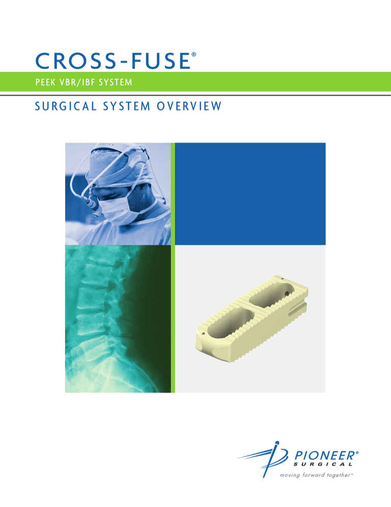
SURGICAL TECHNIQUE
C ROSS - F U SE ®
P EEK VBR /IBF SYSTEM
SURGICAL SYSTEM OVERVIEW
CROSS-FUSE
PEEK VBR/IBF SYSTEM
2
SURGICAL TECHNIQUE
Table of Contents
INTRODUCTION
Indications, Warnings, Precautions, Contraindications
1
System Overview
3
SURGICAL TECHNIQUE OVERVIEW
Step 1 – EMG Monitoring
5
Step 2 – Disc Space Access
5
Step 3 – Visualization of the Operative Space
5
Step 4 – Discectomy/End Plate Preparation
5
Step 5 – Trial Spacers
5
Step 6 – Implant Selection
6
Step 7 – Implant Insertion
7
Step 8 – Radiographic Verification
7
8
PRODUCT INFORMATION
Parts List
3
CROSS-FUSE
PEEK VBR/IBF SYSTEM
Introduction
INDICATIONS
Cross-Fuse PEEK implants are indicated as both Interbody Fusion Devices (IBFs) and Vertebral Body Replacements (VBRs).
Pioneer VBRs are intended for use in the thoracolumbar spine (T1-L5) for partial replacement (i.e., partial vertebrectomy) of a
diseased vertebral body resected or excised for the treatment of tumors in order to achieve anterior decompression of the spinal
cord and neural tissues, and to restore the height of a collapsed vertebral body. Pioneer VBRs are also indicated for treating
fractures of the thoracic and lumbar spine. Pioneer VBRs are designed to restore the biomechanical integrity of the anterior, middle
and posterior spinal column, even in the absence of fusion for a prolonged period of time. Pioneer VBRs must be used with the
Pioneer Quantum® Spinal Fixation System or supplemental internal fixation systems cleared for the conditions listed above (i.e.,
tumor or trauma of T1-L5). Additionally, Pioneer VBRs are intended to be used with bone graft.
Pioneer IBFs are indicated for intervertebral body fusion of the spine in skeletally mature patients. Pioneer IBFs are designed for
use with autogenous bone graft to facilitate fusion. One device may be used per intervertebral space. Pioneer IBFs are intended to
be used with supplemental spinal fixation cleared for the implanted level, such as the Quantum System.
Lumbar IBFs are also intended for use at either one level or two contiguous levels in the lumbar spine, from L2 to S1, for the
treatment of degenerative disc disease (DDD) with up to Grade 1 spondylolisthesis. DDD is defined as back pain of discogenic
origin with degeneration of the disc confirmed by history and radiographic studies. Lumbar IBFs are to be used in patients who
have had six months of non-operative treatment.
WARNINGS
One of the potential risks identified with this system is death. Other potential risks which may require additional surgery, include:
• device component fracture
• loss of fixation
• non-union
• fracture of the vertebrae
• neurological injury
• vascular or visceral injury
The components of this device are manufactured from a radiolucent polymer and include either Titanium or Tantalum (Ta)
radiographic markers. Mixing of implant components with different materials is not recommended, for metallurgical, mechanical
and functional reasons.
PRECAUTIONS
The implantation of IBFs, VBRs and supplemental internal fixation should be performed only by experienced spinal surgeons with
specific training in the use of this system as this is a technically demanding procedure presenting a risk of serious injury to the
patient. Preoperative planning and patient anatomy should be considered when selecting implant size and supplemental internal
fixation.
IBFs and VBRs (regardless of the indication for which they are designated) are designed to withstand both full load bearing and the
loads associated with long-term use which could result from the presence of non-union or delayed union. To ensure load-bearing
ability and the loads associated with long-term use, supplemental fixation is required with the use of this device. Please refer to the
product specific insert for these types of device systems for additional information, (i.e., descriptions, indications, etc.).
1
SURGICAL TECHNIQUE
While proper selection can help minimize risks, the size and shape of human bones present limitations on the size, shape, and
strength of implants. Internal fixation devices cannot withstand activity levels equal to those placed on normal healthy bone.
These devices can break when subjected to the increased loading associated with delayed union or nonunion. Typically, internal
fixation appliances are load-sharing devices which hold a fracture in alignment until healing occurs. If healing is delayed, or does
not occur, an implant could eventually break due to fatigue. Loads produced by weight bearing and activity levels will dictate the
longevity of the implant. The patient should understand that stress on an implant could involve more than weight bearing. In the
absence of solid bony union, patient weight alone, muscular forces associated with moving, or repeated stresses of apparent
relatively small magnitude, can compromise the implant. Patients should be fully informed of the risks of implant failure.
Correct handling of the implant is extremely important. Notches or scratches put in the implant during the course of surgery may
also contribute to breakage. Alterations will produce defects in surface finish and internal stresses which may become the focal
point for eventual breakage of the implant. Surgical implants must never be reused. An explanted implant should never be reimplanted. Even though the device appears undamaged, it may have small defects and internal stress patterns which may lead to
early breakage.
After treatment of an interbody or vertebral body fracture and identification of the presence of fusion only the supplemental fixation
component of a vertebral body replacement system should be removed.
Certain degenerative diseases or underlying physiological conditions such as diabetes or rheumatoid arthritis may alter the healing
process, thereby increasing the risk of implant breakage.
Patients with previous spinal surgery at the level(s) to be treated may have different clinical outcomes compared to those without a
previous surgery.
CONTRAINDICATIONS
Use of Pioneer IBFs is contraindicated when:
• An active infection is present at the operative site or with an allergy to PEEK, titanium, titanium alloy or tantalum
• A prior fusion at the level(s) to be treated
• Any condition not described in the indications for use is present
Use of the Pioneer VBRs is contraindicated when:
• There is active systemic infection, infection localized to the site of the proposed implantation, or when the patient has
demonstrated allergy or foreign body sensitivity to any of the implant materials.
• Severe osteoporosis may prevent adequate fixation and thus preclude the use of this or any other orthopaedic implant.
• Conditions that may place excessive stresses on bone and implants, such as severe obesity or degenerative diseases, are relative contraindications. The decision whether to use these devices in such conditions must be made by the physician taking into account the risks versus the benefits to the patient.
• Use of these implants is relatively contraindicated in patients whose activity, mental capacity, mental illness, alcoholism, drug abuse, occupation, or lifestyle may interfere with their ability to follow postoperative restrictions and who may place undue stresses on the implant during bony healing and may be at a higher risk of implant failure.
*See product insert for complete labeling limitations related to this device.
2
CROSS-FUSE
PEEK VBR/IBF SYSTEM
Introduction
SYSTEM OVERVIEW - IMPLANT
1
BULLET-SHAPED TIP
4
Aids in ease of implant insertion.
2
BACK-CUTTING TEETH
2
Resist migration.
3
3
ANATOMICALLY DESIGNED
1mm of convexity. Parallel or
lordotic option available.
4
LARGE G RAFT AREA
5
1
For maximum fusion potential.
6
5
PEEK-OPTIMA MATERIAL
A material with proven clinical history
which provides structural strength to
support the anterior column of the spine.
It is also radiolucent and biocompatible.
6
HIGHLY VISIBLE TANTALUM MARKERS
Provides optimal placement verification
through radiographic imaging.
6° Lordosis
NOTE: Anterior is written on implant for proper
orientation during implantation.
3
Posterior
Anterior
SURGICAL TECHNIQUE
SYSTEM OVERVIEW - INSTRUMENTS
50mm
40mm
Detachable Trial Spacers
35-DTRLX-Y-Z
• Innovative design
• Spacers are approximately 1mm shorter in height than the
corresponding implant
55mm
45mm
• Detachable quick release handle for ease of use
Heights:
9mm -15mm, in 2mm increments
Lordosis: 0°, 6°
Widths:
14mm, 18mm, 22mm
The innovative trial spacer design provides
incremental grooves. The first indent on all trial
spacers is 40mm. Each subsequent indent is 5mm.
X = Width, Y = Height and Z = Lordosis
T-Handle
Inserter
Slaphammer
Tamp
35-THANDLE
35-INSERTER-X
30-T-SLAPHAMMER
35-TAMP
• Quick release allows for ease
of use
Widths:
14mm, 18mm*
*22mm implants utilize the 18mm Inserter
• Efficient in removing implants
or Trial Spacers, if necessary
• For final positioning
• Trial Spacer Key-Lock and
Slaphammer attachment
4
CROSS-FUSE
PEEK VBR/IBF SYSTEM
Surgical Technique
STEP 1 EMG MONIT ORING
Many surgeons choose to use EMG monitoring with the Cross-Fuse
Interbody Fusion Device (IBF) and Vertebral Body Replacement (VBR)
system approach.
STEP 2 DISC SPACE ACCESS
A lateral retractor system is necessary to gain access to the disc
space area. Access the operative site and retract tissues to allow for
complete exposure and visualization.
STEP 3 VISUALIZATION OF THE OPERATIVE SPACE
Attach a light source to the retractor for better visualization. Bipolar
cautery is used to prepare disc annulus visualization.
STEP 4 DISCECTOMY/END PLATE PREPARATION
Prepare the resected space by performing a discectomy. Use
Pioneer’s preparatory instruments provided (including Lateral
Fusion™ Instruments) to prepare the resected space. Select the
desired instruments and/or shavers to debulk disc material and to
remove cartilaginous endplates or vertebra, as necessary. Remove
loose tissue with pituitary rongeurs. Perforate the bony endplates to
expose bleeding bone.
STEP 5 TRIAL SPACERS
If significant disc space collapse is present, use the
9mm spreader from the Lateral Fusion Instruments as
50mm
an initiator (6mm height x 9mm width). See Figure 1.
Figure 1 - Lateral Fusion 9mm width spreader
5
SURGICAL TECHNIQUE
Insert a trial spacer (Figure 2) into the resected space to determine
the desired implant width, height, and angle (parallel or 6° lordosis)
by using radiographic images. The first groove on all trial spacers
is 40mm, with subsequent grooves every 5mm. Insert a trial
spacer based on preferred implant size.
Figure 2 - Trial Spacer
NOTE: The 40mm groove on all trial spacers is for consistency, the
40mm implants are optional and must be ordered individually.
Remove the detachable quick-release handle of the trial spacer
from the shaft (Figure 3). Verify the trial spacer size and placement
in the resected space using fluoroscopic guidance.
STEP 6 IMPLANT SELECTION
Standard Implant Set
There are 22 implants in the Standard Implant Set (9mm-15mm
heights in 2mm increments and 45mm, 50mm and 55mm lengths).
Standard implants are all parallel and available in 14mm or 18mm
Figure 3 - Quick Release Handle
widths. (Please refer to the Standard Implant Set chart on
Page 8 for a complete list of implant sizes.)
Optional Lordotic Implant Set
A set that includes 19 optional lordotic implants is also available.
The implants are available in 14mm and 18mm widths, with a 6°
lordotic angle. (Please refer to the Optional Lordotic Implant Set
chart on Page 8 for a complete list of implant sizes.)
Optional Individual Implant Set
There are also 53 optional individual implants available upon
request. (Please refer to the Optional Loaner Sets chart on page 9
for a complete list of implant sizes.)
6
CROSS-FUSE
PEEK VBR/IBF SYSTEM
STEP 7 IMPLANT INSERTION
Pack the selected implant with indicated graft material. Attach the
selected implant to the inserter (Figure 4). Ensure that the implant
is fully seated and flush to the inserter. Insert implant across the
resected space. Confirm implant placement by utilizing A/P and
lateral fluoroscopy.
Figure 4 - Implant Insertion
NOTE: The 14mm width implants utilize the 14mm Inserter. Both the
18mm and 22mm width implants utilize the 18mm Inserter.
STEP 8 RADIOGRAPHIC VERIFICATION
With the patient in the lateral position, verify proper implant
placement with A/P and lateral fluoroscopic images. The highly
visible tantalum markers provide 3-D radiographic size and
placement verification. Ensure an accurate A/P and lateral C-Arm
fluoroscopic image is obtained. For lateral imaging, position the
2mm
1mm
Figure 5 - 14mm and 18mm Width A/P View
C-Arm machine such that the superior endplate of the level being
imaged is parallel and looks like a flat black line. The A/P image will
require parallel superior endplates of the level being imaged as well
as an image positioning the spinous process in the center of the
vertebral body.
14mm and 18mm Width
Figure 6 - 14mm and 18mm Width Lateral View
The A/P view should show three vertical markers (Figure 5).
The lateral view should show two vertical markers. The anterior side
may have two vertical pins close to one another (Figure 6).
22mm Width
The A/P view should show two vertical markers at the anterior and
2mm
3mm
Figure 7 - 22mm Width A/P View
posterior faces of the implant, with one dot in the center (Figure 7).
The lateral view should show one vertical marker and two horizontal
markers centered vertically at the anterior and posterior faces of the
implant (Figure 8).
7mm
Figure 8 - 22mm Width Lateral View
7
SURGICAL TECHNIQUE
Product Information
See implant charts for measurements.
A) Anterior (Max) Height
B) Width
C) Length
STANDARD IMPLANT SET (35-LS-IMP-L)
OPTIONAL LORDOTIC IMPLANT SET (35-LS-IMP-L-F)
Part Number
Anterior
Height (A)
(mm)
Posterior
Height
(mm)
Width
(B)
(mm)
Length
(C)
(mm)
Lordosis
Graft Vol.
(cc’s)
Part Number
Anterior
Height (A)
(mm)
Posterior
Height
(mm)
Width
(B)
(mm)
Length
(C)
(mm)
Lordosis
Graft Vol.
(cc’s)
35-1445-9
9
9
14
45
0˚
2
35-1445-9-6
9
7.5
14
45
6˚
2
35-1450-9
9
9
14
50
0˚
3
35-1450-9-6
9
7.5
14
50
6˚
2
35-1455-9
9
9
14
55
0˚
3
35-1455-9-6
9
7.5
14
55
6˚
2
35-1845-9
9
9
18
45
0˚
3
35-1850-9-6
9
7
18
50
6˚
3
35-1850-9
9
9
18
50
0˚
4
35-1855-9-6
9
7
18
55
6˚
4
35-1855-9
9
9
18
55
0˚
4
35-1445-11-6
11
9.5
14
45
6˚
3
35-1445-11
11
11
14
45
0˚
3
35-1450-11-6
11
9.5
14
50
6˚
3
35-1450-11
11
11
14
50
0˚
3
35-1455-11-6
11
9.5
14
55
6˚
3
35-1455-11
11
11
14
55
0˚
4
35-1850-11-6
11
9
18
50
6˚
4
35-1845-11
11
11
18
45
0˚
4
35-1855-11-6
11
9
18
55
6˚
5
35-1850-11
11
11
18
50
0˚
4
35-1445-13-6
13
11.5
14
45
6˚
3
35-1855-11
11
11
18
55
0˚
5
35-1450-13-6
13
11.5
14
50
6˚
4
35-1445-13
13
13
14
45
0˚
3
35-1455-13-6
13
11.5
14
55
6˚
4
35-1450-13
13
13
14
50
0˚
4
35-1850-13-6
13
11
18
50
6˚
5
35-1455-13
13
13
14
55
0˚
4
35-1855-13-6
13
11
18
55
6˚
6
35-1845-13
13
13
18
45
0˚
5
35-1450-15-6
15
13.5
14
50
6˚
4
35-1850-13
13
13
18
50
0˚
5
35-1455-15-6
15
13.5
14
55
6˚
5
35-1855-13
13
13
18
55
0˚
6
35-1850-15-6
15
13
18
50
6˚
6
35-1450-15
15
15
14
50
0˚
4
35-1855-15-6
15
13
18
55
6˚
7
35-1455-15
15
15
14
55
0˚
5
35-1850-15
15
15
18
50
0˚
6
35-1855-15
15
15
18
55
0˚
7
8
CROSS-FUSE
PEEK VBR/IBF SYSTEM
OPTIONAL LOANER SETS
35-LS-OPTIONAL
35-LS-OPTION-22
Part Number
Anterior
Height (A)
(mm)
Posterior
Height
(mm)
Width
(B)
(mm)
Length
(C)
(mm)
Lordosis
Graft Vol.
(cc’s)
Part Number
Anterior
Height (A)
(mm)
Posterior
Height
(mm)
Width
(B)
(mm)
Length
(C)
(mm)
Lordosis
Graft Vol.
(cc’s)
35-1440-7
7
7
14
40
0˚
1
35-2245-9
9
9
22
45
0˚
3
35-1445-7
7
7
14
45
0˚
2
35-2250-9
9
9
22
50
0˚
3
35-1450-7
7
7
14
50
0˚
2
35-2255-9
9
9
22
55
0˚
4
35-1440-9
9
9
14
40
0˚
2
35-2245-9-6
9
6.7
22
45
6˚
2
35-1840-9
9
9
18
40
0˚
3
35-2250-9-6
9
6.7
22
50
6˚
3
35-1845-9-6
9
7
18
45
6˚
3
35-2255-9-6
9
6.7
22
55
6˚
3
35-1440-11
11
11
14
40
0˚
2
35-2245-11
11
11
22
45
0˚
4
11
11
22
50
0˚
4
35-1840-11
11
11
18
40
0˚
3
35-2250-11
35-1845-11-6
11
9
18
45
6˚
3
35-2255-11
11
11
22
55
0˚
5
35-1440-13
13
13
14
40
0˚
3
35-2245-11-6
11
8.7
22
45
6˚
3
35-1840-13
13
13
18
40
0˚
4
35-2250-11-6
11
8.7
22
50
6˚
4
35-1845-13-6
13
11
18
45
6˚
4
35-2255-11-6
11
8.7
22
55
6˚
4
13
13
22
45
0˚
4
13
22
50
0˚
5
35-1440-15
15
15
14
40
0˚
3
35-2245-13
35-1445-15
15
15
14
45
0˚
4
35-2250-13
13
35-1845-15
15
15
18
45
0˚
5
35-2255-13
13
13
22
55
0˚
6
5
35-2245-13-6
13
10.7
22
45
6˚
4
35-2250-13-6
13
10.7
22
50
6˚
4
35-2255-13-6
13
10.7
22
55
6˚
5
35-2245-15
15
15
22
45
0˚
5
35-2250-15
15
15
22
50
0˚
6
35-2255-15
15
15
22
55
0˚
7
35-2245-15-6
15
12.7
22
45
6˚
5
35-2250-15-6
15
12.7
22
50
6˚
5
35-2255-15-6
15
12.7
22
55
6˚
6
35-1845-15-6
15
13
18
45
6˚
35-LS-OPTION-LG
Anterior
Height (A)
(mm)
Posterior
Height
(mm)
Width
(B)
(mm)
Length
(C)
(mm)
Lordosis
35-1850-17
17
17
18
50
0˚
7
35-1850-17-6
17
15
18
50
6˚
7
35-1855-17
17
17
18
55
0˚
7
35-1855-17-6
17
15
18
55
6˚
8
35-1860-17-6
17
15
18
60
6˚
8
35-1860-9
9
7
18
60
0˚
4
35-1860-9-6
9
7
18
60
6˚
4
Part Number
9
Graft Vol.
(cc’s)
35-1860-11
11
9
18
60
0˚
5
35-1860-11-6
11
9
18
60
6˚
5
35-1860-13
13
11
18
60
0˚
6
35-1860-13-6
13
11
18
60
6˚
6
35-1860-15
15
13
18
60
0˚
7
35-1860-15-6
15
13
18
60
6˚
7
SURGICAL TECHNIQUE
Notes
10
CROSS-FUSE
PEEK VBR/IBF SYSTEM
Notes
11
SURGICAL TECHNIQUE
12
© 2010 Pioneer Surgical Technology. All rights reserved.
The trade name Pioneer Surgical as used herein and
elsewhere refers to the legal entity Pioneer Surgical
Technology, Inc. Pioneer Surgical owns the following
trademarks: Pioneer, Cross-Fuse, Fusion, Quantum and
Moving Forward Together. The following trademarks are
registered in the U.S.: Pioneer, Cross-Fuse and Quantum.
Authorized EC Representative:
RSQR Ltd.
Room 402 Ludgate House
107-111 Fleet Street
London EC4A 2AB
www.rsqa.co.uk
info@rsqa.co.uk
Pioneer Surgical Technology BV
Princenhof Park 10, 3972 NG Driebergen,
The Netherlands
Tel. +31 30 693 47 20 / Fax. +31 30 693 47 21
www.pioneersurgical.eu
info@pioneersurgical.eu
CoC Utrecht 30214021
Pioneer Surgical Technology
375 River Park Circle
Marquette, MI 49855
(800) 557-9909
www.pioneersurgical.com
0086
MKT-132-D/112297


