Resistance Bridge 1009885
advertisement

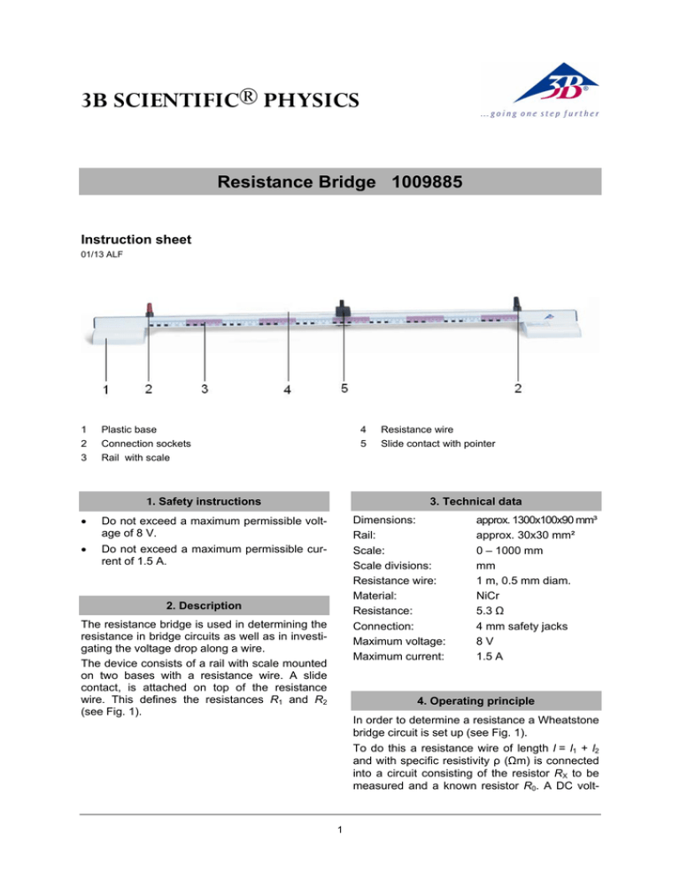
3B SCIENTIFIC® PHYSICS Resistance Bridge 1009885 Instruction sheet 01/13 ALF 1 2 3 Plastic base Connection sockets Rail with scale 4 5 3. Technical data 1. Safety instructions • Do not exceed a maximum permissible voltage of 8 V. • Do not exceed a maximum permissible current of 1.5 A. Resistance wire Slide contact with pointer Dimensions: Rail: Scale: Scale divisions: Resistance wire: Material: Resistance: Connection: Maximum voltage: Maximum current: 2. Description The resistance bridge is used in determining the resistance in bridge circuits as well as in investigating the voltage drop along a wire. The device consists of a rail with scale mounted on two bases with a resistance wire. A slide contact, is attached on top of the resistance wire. This defines the resistances R1 and R2 (see Fig. 1). approx. 1300x100x90 mm³ approx. 30x30 mm² 0 – 1000 mm mm 1 m, 0.5 mm diam. NiCr 5.3 Ω 4 mm safety jacks 8V 1.5 A 4. Operating principle In order to determine a resistance a Wheatstone bridge circuit is set up (see Fig. 1). To do this a resistance wire of length l = l1 + l2 and with specific resistivity ρ (Ωm) is connected into a circuit consisting of the resistor RX to be measured and a known resistor R0. A DC volt- 1 age U is applied to this circuit. The ammeter is used to measure the current flowing between the point D and the moveable tapping point C located on the resistance wire. The partial resistances of the wire R1 and R2 can be varied using the slide contact on the resistance wire. Now it is important to calibrate the measurement bridge, i.e. to adjust the slide contact so that there is no voltage between points C and D and thus a current no longer flows. The partial resistances are: l l R1 = ρ ⋅ 1 and R 2 = ρ ⋅ 2 F F 5. Sample experiments For the resistance ratios the following then holds true: 5.1 Determining resistance in a Wheatstone bridge circuit Additionally required: 1 AC/DC Power Supply 12 V, 3 A (230 V, 50/60 Hz) 1002776 or 1 AC/DC Power Supply 12 V, 3 A (115 V, 50/60 Hz) 1002775 1 Zero Galvanometer CA 403 1002726 1 Resistance Decade 1 Ω 1002730 or 1 Resistance Decade 10 Ω 1002731 or 1 Resistance Decade 100 Ω 1002732 1 Incandescent lamp with socket 8 Experiment cables (500 mm) 1 Switch (optional) RX R l = 1 = 1 R0 R2 l2 • Connect up the experiment setup as illustrated (see Fig. 1). • An incandescent lamp is used as the unknown resistance. • A voltage of 4 to 6 V is applied. • Close switch K and slowly move the slide contact from A to B to A again. • At the same time observe the deflection of the ammeter. When the pointer deflection in the proximity of point A is zero, this means that the value of R0 is very high and that it must be reduced. If the zero value is in the proximity of point B, then the value of R0 is too low and must be increased. • Select the R0 value so that when the power is switched on again the pointer of the ammeter does not deflect when the slide contact is in the middle of the wire, i.e. the measurement bridge is calibrated. • If there is no appropriate resistance available, use a resistor R0, for which the pointer's deflection is smallest and then carry out the calibration. • Obtain readings of partial lengths of the resistance wire. • Repeat the experiment with varied voltage levels, enter your findings in a table and compute the resistance RX. whereby F is the cross-sectional area of the wire. From this we can deductively compute the unknown resistance: l R X = R0 ⋅ 1 l2 The resistor R0 should be selected so that upon calibration of the bridge l1 and l2 are approximately equal, in order to keep the error to a minimum. Fig. 1 5.2 Determine the specific resistivity ρ of a wire • 2 Experiment set-up according to Fig. 1, but this time use a resistance wire with a length from 1 to 3 m instead of the incandescent lamp. • Measure the length l and diameter d of the wire used and from this compute the crosssectional area F. • Determine the resistance RX as described under 5.1. • For computed resistance RX the following is true: • The following is true for its specific resistance: ρ = RX ⋅ • F l Repeat the experiment with various voltages and wires of varying lengths, enter the data into a table and work out the mean value. l F Whereby ρ is the specific resistivity, l is the length of the wire in m and F is its crosssectional area in m2. RX = ρ ⋅ Fig. 2 Determining resistance in a Wheatstone bridge circuit 3B Scientific GmbH ▪ Rudorffweg 8 ▪ 21031 Hamburg ▪ Germany ▪ www.3bscientific.com Subject to technical amendments © Copyright 2013 3B Scientific GmbH


