Comparative Study Of The PML And C-COM Mesh
advertisement

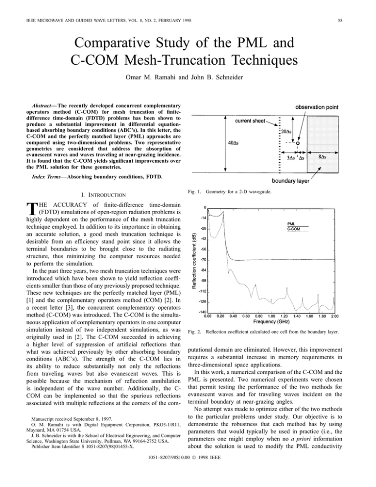
IEEE MICROWAVE AND GUIDED WAVE LETTERS, VOL. 8, NO. 2, FEBRUARY 1998 55 Comparative Study of the PML and C-COM Mesh-Truncation Techniques Omar M. Ramahi and John B. Schneider Abstract— The recently developed concurrent complementary operators method (C-COM) for mesh truncation of finitedifference time-domain (FDTD) problems has been shown to produce a substantial improvement in differential equationbased absorbing boundary conditions (ABC’s). In this letter, the C-COM and the perfectly matched layer (PML) approachs are compared using two-dimensional problems. Two representative geometries are considered that address the absorption of evanescent waves and waves traveling at near-grazing incidence. It is found that the C-COM yields significant improvements over the PML solution for these geometries. Index Terms—Absorbing boundary conditions, FDTD. Fig. 1. Geometry for a 2-D waveguide. I. INTRODUCTION T HE ACCURACY of finite-difference time-domain (FDTD) simulations of open-region radiation problems is highly dependent on the performance of the mesh truncation technique employed. In addition to its importance in obtaining an accurate solution, a good mesh truncation technique is desirable from an efficiency stand point since it allows the terminal boundaries to be brought close to the radiating structure, thus minimizing the computer resources needed to perform the simulation. In the past three years, two mesh truncation techniques were introduced which have been shown to yield reflection coefficients smaller than those of any previously proposed technique. These new techniques are the perfectly matched layer (PML) [1] and the complementary operators method (COM) [2]. In a recent letter [3], the concurrent complementary operators method (C-COM) was introduced. The C-COM is the simultaneous application of complementary operators in one computer simulation instead of two independent simulations, as was originally used in [2]. The C-COM succeeded in achieving a higher level of suppression of artificial reflections than what was achieved previously by other absorbing boundary conditions (ABC’s). The strength of the C-COM lies in its ability to reduce substantially not only the reflections from traveling waves but also evanescent waves. This is possible because the mechanism of reflection annihilation is independent of the wave number. Additionally, the CCOM can be implemented so that the spurious reflections associated with multiple reflections at the corners of the comManuscript received September 8, 1997. O. M. Ramahi is with Digital Equipment Corporation, PKO3-1/R11, Maynard, MA 01754 USA. J. B. Schneider is with the School of Electrical Engineering, and Computer Science, Washington State University, Pullman, WA 99164-2752 USA. Publisher Item Identifier S 1051-8207(98)01455-X. Fig. 2. Reflection coefficient calculated one cell from the boundary layer. putational domain are eliminated. However, this improvement requires a substantial increase in memory requirements in three-dimensional space applications. In this work, a numerical comparison of the C-COM and the PML is presented. Two numerical experiments were chosen that permit testing the performance of the two methods for evanescent waves and for traveling waves incident on the terminal boundary at near-grazing angles. No attempt was made to optimize either of the two methods to the particular problems under study. Our objective is to demonstrate the robustness that each method has by using parameters that would typically be used in practice (i.e., the parameters one might employ when no a priori information about the solution is used to modify the PML conductivity 1051–8207/98$10.00 1998 IEEE 56 IEEE MICROWAVE AND GUIDED WAVE LETTERS, VOL. 8, NO. 2, FEBRUARY 1998 Fig. 3. Boundary layer to determine near-grazing incidence reflection. Fig. 4. Solution at observation point corresponding to an incidence angle of 82 : Fig. 5. Frequency domain response at observation point. II. TWO-DIMENSIONAL WAVEGUIDE profile or the C-COM boundary-operator coefficients). For the PML conductivity, it is our observation that a profile with cubic spatial dependence and a theoretical reflection at normal incidence of 10 consistently produces high-quality results when the PML thickness is eight cells or more. Therefore, these conductivity parameters were used in the cases studied here. The C-COM method used in this work is based on Higdon’s third-order ABC. The two complementary operators are obtained from the discrete form of the following boundary operators (see [2] and [3] for details): (1) The uniform rectangular cross-section waveguide has been used extensively as a testbed for evaluating the relative performance of mesh truncation techniques. Here, we consider a 2-D perfectly conducting parallel plate waveguide with a cross section of 0.6 m, as shown in Fig. 1. For the dominant mode, the waveguide will have a cutoff frequency of 0.25 GHz. Below the cutoff frequency, the dominant wave evanesces, while above cuttoff, it is purely traveling. The waveguide is excited by an impressed current sheet that is transparent to waves that are reflected off the terminal boundaries. The current sheet has a spatial distribution across the waveguide that produces the dominant mode. The temporal form of the current source is given by the convolution where (3) (2) otherwise is introduced for stability and is directly dependent The on the FDTD cell size. Empirical studies have shown that is sufficient for stabilizing the solution. For the is set to zero since instability is not a waveguide problem problem because of the absence of corner regions [4]. where and The distinct advantage of this pulse is that its high-frequency energy is strongly suppressed in order to avoid undesired grid dispersion. The FDTD simulation uses a uniform space step of mm and a time step of s, where is the Courant limit. IEEE MICROWAVE AND GUIDED WAVE LETTERS, VOL. 8, NO. 2, FEBRUARY 1998 On the right end, the waveguide is terminated with either the PML or the C-COM boundary layer. Since the interest is in the reflection from the terminal boundary, the left end of the waveguide is extended to a distance such that the terminal reflection is absent from the solution time window. The simulation was performed for 8192 time steps. The observation point is positioned one cell from the mesh truncation layer as shown in Fig. 1. At the observation point the reflection coefficient is calculated as (4) denotes the Fourier transform operation, is the where numerically exact solution, and is the solution obtained using either C-COM or PML. The numerically exact solution is calculated with the two ends of waveguide located at a distance far enough from the observation point to eliminate reflections from the solution window of 8192 time steps. Fig. 2 shows the reflection coefficient obtained using the C-COM and the PML techniques, with both using an eightcell-wide boundary layer. These results show the C-COM achieving a substantial improvement over the PML for the same size layer. Such improvement is especailly pronounced over the evanescent energy spectrum. It must be stated, however, that the C-COM, in the case of the waveguide problem, requires doubling the storage requirements for the fields in the boundary layer, thus giving rise to a total of six memory locations for each FDTD cell. On the other hand, the PML requires splitting only one field component, thus resulting in a total of four memory locations for each FDTD cell. III. NEAR-GRAZING INCIDENCE REFLECTION Waves impinging on terminal boundaries at near-grazing incidence (highly oblique angles of incidence with respect to the normal) are usually poorly absorbed by boundary operators and also by absorptive media. In this test, we construct a numerical experiment to test the effectiveness of a 16-layer C-COM and PML for absorbing waves with highly oblique 57 angles of incidence. For this, we consider reflection from one side of the FDTD domain as shown in Fig. 3. The three other sides of the domain are far enough from the observation point such that the artificial reflections are absent from the solution time window. Next, an impressed current source is positioned two cells above the boundary layer, as shown in Fig. 3, and an observation point is located at where denotes the location of the source. The observation point corresponds to rays reflected off the terminal boundary having an incidence angle of 82 The temporal excitation of the source and the space and time steps are as before. The pulse arriving at the observation points is shown in Fig. 4. The C-COM solution is seen to give a better match to the reference solution than the PML solution. The strength of the C-COM is more obvious when the results are plotted in the frequency domain as shown in Fig. 5. A simulation of 1000 time steps was used in the calculation of the frequency response. Note that the C-COM solution has a maximum error of approximately 0.5 dB, whereas the PML error exceeds 3 dB. IV. CONCLUSION This letter presented a comparative study between the C-COM and the PML mesh truncation techniques. The comparison focused on the performance of the two techniques in absorbing evanescent wave and highly oblique traveling waves. For the problems considered, the C-COM was found to yield an appreciable improvement over the PML method. REFERENCES [1] J.-P. Berenger, “A perfectly matched layer for the absorption of electromagnetic waves,” J. Comput. Phys., vol. 114, pp. 185–200, 1994. [2] O. M. Ramahi, “Complementary boundary operators for wave propagation problems,” J. Comput. Physics, vol. 133, pp. 113–128, 1997. [3] O. M. Ramahi, “Concurrent implementation of the complementary operators method in 2D space,” IEEE Microwave Guided Wave Lett., vol. 7, pp. 165–167, June 1997. [4] O. M. Ramahi, “Efficient characterization of microstrip structures using higher order boundary operators,” in URSI Radio Science Meet., Program and Abstracts, July 13–18, 1997, p. 187.

