Seismic Technical Guide — Compression Posts (English
advertisement

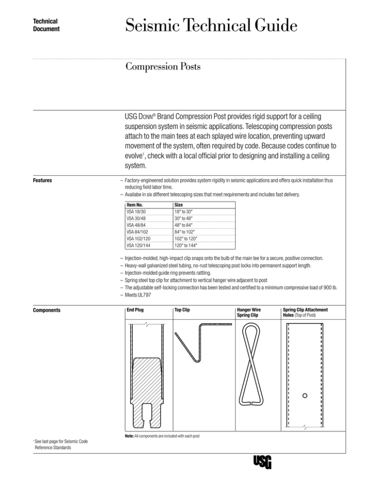
Technical Document Seismic Technical Guide Compression Posts USG Donn® Brand Compression Post provides rigid support for a ceiling suspension system in seismic applications. Telescoping compression posts attach to the main tees at each splayed wire location, preventing upward movement of the system, often required by code. Because codes continue to evolve1, check with a local official prior to designing and installing a ceiling system. Features –Factory-engineered solution provides system rigidity in seismic applications and offers quick installation thus reducing field labor time. – Availabe in six different telescoping sizes that meet requirements and includes fast delivery. Item No. VSA 18/30 VSA 30/48 VSA 48/84 VSA 84/102 VSA 102/120 VSA 120/144 Size 189 to 309 309 to 489 489 to 849 849 to 1029 1029 to 1209 1209 to 1449 – Injection-molded, high-impact clip snaps onto the bulb of the main tee for a secure, positive connection. –Heavy-wall galvanized steel tubing, no-rust telescoping post locks into permanent support length. – Injection-molded guide ring prevents rattling. – Spring steel top clip for attachment to vertical hanger wire adjacent to post – The adjustable self-locking connection has been tested and certified to a minimum compressive load of 900 lb. – Meets UL797 End Plug Top Clip Components 1 See last page for Seismic Code Reference Standards Note: All components are included with each post Hanger Wire Spring Clip Spring Clip Attachment Holes (Top of Post) Installation Application Step 1 Fit top clip into the opening of the post. Step 2 Snap compression post onto main tee bulb next to vertical hanger wire. Step 3 Bring compression post to vertical with hanger and extend post for snug fit against structure. Step 4 Loop spring clip around vertical hanger wire and connect to holes on top of post. Step 5 Mechanically fasten end plug of post to main tee bulb. Step 6 Fasten compression post to structure with the appropriate mechanical fastener. top clip (mechanically fastened) structure spring clip spring clip attachment holes vertical hanger wire adjacent to post spring clip inserts in hole in post structure top clip splay wire secured to structure hanger wire 45˚ or less 45˚ or less 45˚ or less 45˚ or less bulb clip (mechanically fastened) compression post ceiling cross tee install within 2" of cross tee intersection spring clip inserts in hole in post vertical hanger wire adjacent to post structure splay wire secured to structure 45˚ or less 45˚ or less 45˚ or less 45˚ or less cross tee 2 Compression Posts install within 2" of cross tee main tee main tee 2" max. 2" max. a fastener or splay wires maybe inserted into the tab of the post and through a convenience hole in the main tee bulb Installation Alternative Materials T he USG Donn Brand compression post is an engineered solution designed to work with USG Donn Brand Suspension Systems when required by code. The USG Donn Brand compression post is an option for almost every project, however it is not necessary to use the USG Donn Brand compression post when installing USG Donn Brand Suspension Systems. Any steel member with sufficient strength is allowed by code and may be suitable for use as a compression post. Below are some common, light gauge steel members provided by others that are typically used as alternates for compression posts and their typical associated allowable lengths. Alternative Material Typical Allowable Length Alternative Material Typical Allowable Length 13/169 x 13/329 Strut 19 GA 249 3-5/89 x 1-1/49 18GA Stud (362S125-43) 849 1-1/29 x 9/169 x 0.0599 Channel 339 1-1/49 x 1-1/49 Strut 14 GA 849 (2) 3/49 x 1/29 x 0.0599 Channel, Back to Back 399 3-5/89 x 1-1/49 20GA Stud (362S125-30) 859 (2) 1-1/29 x 9/169 x 0.0599 Channel, Back to Back 449 2-1/29 x 1-1/49 25GA Stud (250S125-18) 879 1/29 Diameter EMT Conduit, 0.0429 Wall Thickness 479 158STS 1-5/89 x 1-1/49 x 0.01979 Channel 909 3/49 x 1/29 x 0.0599 Channel 479 1-3/89 x 1-5/89 Strut 12 GA 969 13/169 x 1-5/89 Strut 12 GA 489 1-1/49 x 2-1/29 Strut 14 GA 969 13/169 x 1-5/89 Strut 14 GA 489 1-5/89 x 1-3/89 Strut 12 GA 969 1-1/49 x 3/49 Strut 14 GA 489 1-1/49 Diameter EMT Conduit, 0.0659 Wall Thickness 1029 1-1/49 x 5/89 Strut 19 GA 489 1-5/89 x 1-5/89 Strut 14 GA 1089 1-5/89 x 13/169 Strut 14 GA 489 1-5/89 x 1-5/89 Strut 12 GA 1089 1-5/89 x 13/169 Strut 12 GA 489 1-1/29 Diameter EMT Conduit, 0.0659 Wall Thickness 1189 13/169 x 13/169 Strut 19 GA 549 3-1/49 x 1-5/89 Strut 12 GA 1209 19 x 1-5/89 Strut 12 GA 609 2-7/169 x 1-5/89 Strut 12 GA 1209 1-5/89 x 7/89 Strut 12 GA 609 1-5/89 x 1-5/89 Strut 16 GA 1209 1-5/89 x 13/169 Strut 16 GA 609 1-5/89 x 3-1/49 Strut 12 GA 1209 1-5/89 x 19 Strut 12 GA 609 1-5/89 x 2-7/169 Strut 12 GA 1209 3/49 Diameter EMT Conduit, 0.0499 Wall Thickness 619 (2) 158STS 1-5/89 x 1-1/49 x 0.01979 Channel, Back to Back 1309 19 Diameter EMT Conduit, 0.0579 Wall Thickness 789 29 Diameter EMT Conduit, 0.0659 Wall Thickness 1509 3-5/89 x 1-1/49 16GA Stud (362S125-54) 829 Notes 1. The information provided is for quick reference only. Other restrictions and exemptions may apply. 2. All struts and allowable lengths should be verified by a design professional before use. 3. Wind loads may exceed seismic loads. The distances above may not be suitable for exterior use. 4.Wall molding should not be used as struts. 5. A structural engineer should be consulted for lengths greater than 14ft. Compression Posts 3 Code Compliance Compliance –ICC-ESR-1222 –City of Los Angeles Research Report: RR25764 –CA Division of the State Architect (DSA) IR-A5 Interpretation of Regulations Manual through reference to ICC-ESR-1222 or CA Division of the State Architect (DSA) IR-A6 Change Order and Field Change Approval Processes. –CA Office of Statewide Health Planning and Development (OSHPD) please refer to Code Application Notice 2-1708A.5, pre-approval through ICC-ESR-1222 is recommended. Seismic Code Reference Standards Installation Guidelines for Suspended Ceilings International Building Code (IBC) 2003 IBC 2006 IBC 2009 IBC 2012 IBC American Society of Civil Engineers (ASCE) ASCE7-02 ASCE7-05 ASCE7-05 ASCE7-10 CISCA Zones 0-2 CISCA Zones 0-2 CISCA Zones 0-2 ASTM E580 CISCA Zones 3-4 CISCA Zones 3-4 CISCA Zones 3-4 Ceilings Interior Systems Construction Association (CISCA) or ASTM International (ASTM) International Building Code (IBC) defines Seismic Design Categories A, B, C, D, E, and F. www.iccsafe.org ASCE/SEI 7 Minimum Design Loads for Buildings and Other Structures American Society of Civil Engineers/Structural Engineer Institute (ASCE/SEI) www.asce.org Guidelines for Seismic Restraint for Direct-hung Suspended Ceiling Assemblies (Zones 3-4) Recommendations for Direct-hung Acoustical Tile and Lay-in Panel Ceilings (Zones 0-2) CISCA Ceilings & Interior Systems Construction Association (CISCA) www.cisca.org ASTM Internationl E580/E580M Standard Practice for Installation of Ceiling Suspension Systems for Acoustical TIle and Lay-in Panels in Areas Subject to Earthquate Ground Motions. ASTM International (formerly American Society for Testing and Materials) www.astm.org Further References USG Seismic Ceiling Resource Center Seismic Technical Guides seismicceilings.com Product Information Purpose See usg.com for the most This seismic technical guide up-to-date product information. (STG) is intended as a resource for design professionals, to Installation promote more uniform criteria Must be installed in compliance for plan review and jobsite with ASTM C636, ASTM E580, inspection of projects. This CISCA, and standard industry STG indicates an acceptpractices. able method for achieving compliance with applicable Code Compliance codes and regulations, although The information presented is other methods proposed by correct to the best of our knowldesign professionals may be edge at the date of issuance. considered and adopted. Because codes continue to evolve, check with a local official ICC Evaluation Service, Inc., prior to designing and installing Report Compliance a ceiling system. Other restric- Suspension systems manu- tions and exemptions may apply. factured by USG Interiors, Inc., This is only intended as a quick have been reviewed and are reference. approved by listing in ICC-ES Evaluation Report ESR-1222. Evaluation Reports are subject to reexamination, revision and possible cancellation. Please refer to usgdesignstudio.com or usg.com for current reports. Manufactured by USG Interiors, LLC 550 West Adams Street Chicago, IL 60661 usg.com seismicceilings.com sustainableceilings.com usgdesignstudio.com L.A. Research Report Compliance Donn brand suspension systems manufactured by USG Interiors, Inc., have been reviewed and are approved by listing in the following L.A. Research Report number: 25764. Notice We shall not be liable for incidental and consequential damages, directly or indirectly sustained, nor for any loss caused by application of these goods not in accordance with current printed instructions or for other than the intended use. Our liability is expressly limited to replacement of defective goods. Any claim shall be deemed waived unless made in writing to us within thirty (30) days from date it was or reasonably should have been discovered. Safety First! Follow good safety/industrial hygiene practices during installation. Wear appropriate personal protective equipment. Read MSDS and literature before specification and installation. The following are trademarks of USG Interiors, Inc. or a related company: Donn, DX, DXL, USG in stylized letters. SC2497/rev. 2-12 © 2012, USG Interiors, LLC Printed in U.S.A.

