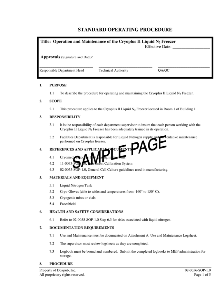
STANDARD OPERATING PROCEDURE
Title: Operation and Maintenance of the Cryoplus II Liquid N2 Freezer
Effective Date: _________________
Approvals (Signature and Date):
_____________________________
Responsible Department Head
1.
4.
5.
6.
8.
This procedure applies to the Cryoplus II Liquid N2 Freezer located in Room 1 of Building 1.
RESPONSIBILITY
3.1
It is the responsibility of each department supervisor to insure that each person working with the
Cryoplus II Liquid N2 Freezer has been adequately trained in its operation.
3.2
Facilities Department is responsible for Liquid Nitrogen supply and Preventative maintenance
performed on Cryoplus freezer.
REFERENCES AND APPLICABLE DOCUMENTS
4.1
Cryomed, Cryoplus II Operating instructions.
4.2
11-0033-SOP-1.0, Instrument Calibration System
4.3
02-0055-SOP-1.0, General Cell Culture guidelines used in manufacturing.
MATERIALS AND EQUIPMENT
5.1
Liquid Nitrogen Tank
5.2
Cryo-Gloves (able to withstand temperatures from -160° to 150° C).
5.3
Cryogenic tubes or vials
5.4
Faceshield
HEALTH AND SAFETY CONSIDERATIONS
6.1
7.
To describe the procedure for operating and maintaining the Cryoplus II Liquid N2 Freezer.
SCOPE
2.1
3.
____________________________
QA/QC
PURPOSE
1.1
2.
_____________________________
Technical Authority
Refer to 02-0055-SOP-1.0 Step 6.3 for risks associated with liquid nitrogen.
DOCUMENTATION REQUIREMENTS
7.1
Use and Maintenance must be documented on Attachment A, Use and Maintenance Logsheet.
7.2
The supervisor must review logsheets as they are completed.
7.3
Logbook must be bound and numbered. Submit the completed logbooks to MEF administration for
storage.
PROCEDURE
Property of Doxpub, Inc.
All proprietary rights reserved.
02-0056-SOP-1.0
Page 1 of 5
8.1
Front Panel Description:
8.1.1
Bar Graph: Twenty five Tri-color LED display indicating actual liquid nitrogen level, start fill
and stop fill levels, alarm level set points, and scale selection. (See operating Instructions for
diagram).
8.1.1.1
A.
B.
C.
D.
8.1.1.2
8.1.1.3
Led Descriptions:
Orange:
Remaining space above stop fill flashing indicator.
Flashing Orange:
The upper is the stop fill indicator, and the high
level alarm set point. The lower is the start fill
indicator and the low level alarm set point.
Green:
Indicates the actual liquid nitrogen level.
Red:
Indicates liquid nitrogen level alarms.
High Level Alarm: When the liquid nitrogen
level rises over the stop fill indicator.
Low Level Alarm: When the liquid nitrogen
level falls below the start fill indicator.
Scale Selection: Two LED’s located at the top of the bar graph indicating which
scale is in use.
A.
Green light on left side of bar graph indicates 2 to 24 inch scale in use.
Scale indicates one inch increments.
B.
Green light on right side of bar graph indicates 2 to 7 inch scale in use.
Scale indicates 1/4 inch increments.
Solenoid Valve: Single LED located under the bar graph.
A.
8.1.1.4
Green: Indicates solenoid valve is open and container is filling.
System Status: Six bar LED’s indicating visual warnings.
A.
Level Sensor:
Indicates level sensor malfunction and sounds
audible alarm.
B.
Fill Coil:
Indicates fill solenoid valve malfunction and sounds
audible alarm.
C.
LN2 Source:
Indicates empty liquid nitrogen source and sound
audible alarm.
D.
Bypass Sensor:
Indicates bypass sensor malfunction or disconnected
and sounds audible alarm.
E.
Vent Coil:
Indicates vent solenoid valve malfunction and
sounds audible alarm.
F.
Stuck Valve:
Indicates solenoid valve is stuck open and sound
audible alarm.
Digital Temperature Display: Seven segment display indicating the actual
temperature under the lid and high temperature alarm set point.
Property of Doxpub, Inc.
All proprietary rights reserved.
02-0056-SOP-1.0
Page 2 of 5


