Application
Guide
Contents
• Applications
• Operating Temperature Range
• Storage
• Refresh Charge
• Commissioning Charge
• Float Operation
• Float Charging Operation • Fast Charging Current Limit
• Float Cycling
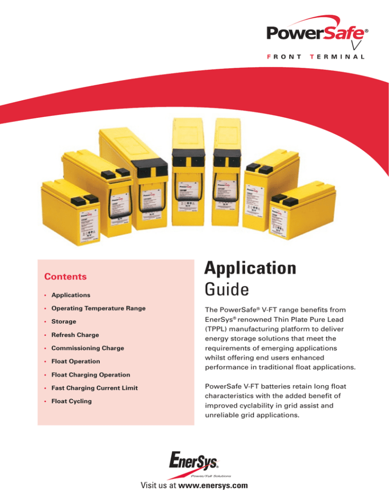
The PowerSafe® V-FT range benefits from
EnerSys® renowned Thin Plate Pure Lead
(TPPL) manufacturing platform to deliver
energy storage solutions that meet the
requirements of emerging applications
whilst offering end users enhanced
performance in traditional float applications.
PowerSafe V-FT batteries retain long float
characteristics with the added benefit of
improved cyclability in grid assist and
unreliable grid applications.
Visit us at www.enersys.com
Applications
Operating Temperature Range
Table 1 below outlines the suitability of PowerSafe® V-FT
batteries for various types of reserve power applications.
The recommended operating temperature for optimum life and
performance is 20°C. However, PowerSafe V-FT monoblocs can
be operated in the temperature range of -30°C to +45°C.
PowerSafe
V-FT
Application
Demands on Battery
Reliable grid
- Stable grid
- Controlled ambient temperature
- Compensated float voltage
- Very little cyclic use
Yes
Grid assist
- Regions where grid is supported
with scheduled outages
- Reasonable temperature control
- Compensated float voltage
- Medium level cyclic use
Yes
- Poor grid stability
- Frequent power outages / scheduled
& unscheduled
- Poor temperature control
- High cyclic use
- Cycles can be shallow / deep
- Low risk for uncontrolled partial state of charge
Yes
- Poor grid stability
- Frequent power outages / scheduled
& unscheduled
- Poor temperature control
- High cyclic use
- Cycles can be shallow / deep
- High risk for uncontrolled partial state of charge
No
Unreliable grid
(Low risk of
PSoC)*
Unreliable grid
(high risk of
PSoC)*
TABLE 1
PowerSafe V-FT
Charge Parameter for Optimised Life and Performance
Reliable grid
TABLE 2
*Partial state of charge
Batteries should be stored in a cool and dry area. Please note
that high temperature increases the rate of self-discharge and
reduces storage life. The maximum storage times before a
refresh charge is required and recommended open circuit voltage
audit intervals are illustrated in table 3.
Storage Time
(Months)
OCV Audit Interval
(Months)
+10 / +50
48
12
+20 / +68
24
12
+30 / +86
12
6
+40 / +104
6
3
TABLE 3
PowerSafe V-FT monoblocs must be given a refresh charge when
the OCV approaches the equivalent of 2.10 Volts per cell or when
the maximum storage time is reached, whichever occurs first.
Refresh Charge
Application
Unreliable grid
(Low risk of
PSoC)*
All lead acid batteries lose capacity when standing on opencircuit because of parasitic chemical reactions. The purity of the
component materials used in the construction of PowerSafe
V-FT batteries results in a very low rate of self-discharge
delivering up to 2 years shelf life at 20°C before a refresh charge
is required.
Temperature
(°C / °F)
Table 2 provides a summary of the operating charging
parameters that will deliver optimum service life and
performance relative to the type of application.
Grid assist
Storage
Temperature compensated float voltage equivalent to
2.29Vpc @ 20°C
Charge current - minimum 0.1C10A, maximum
unlimited, typically 0.5C10A
Boost voltage equivalent to 2.40Vpc @ 20°C to fast
charge
Charge current – minimum 0.1C10A. Maximum
unlimited, typically 0.5C10A
Followed by float voltage with temperature
compensation applied as required
Boost voltage equivalent to 2.40Vpc @ 20°C
to fast charge
Charge current – minimum 0.1C10A. Maximum
unlimited, typically 0.5C10A
Followed by float voltage with temperature
compensation applied as required
A refresh charge should be performed at a constant voltage
equivalent to 2.40Vpc with 0.1C10 Amps current for a period of
24 hours.
Commissioning Charge
Before conducting a capacity discharge or commencing
cycling, the battery must be given a commissioning charge.
In float applications the commissioning charge shall consist of
7 continuous days of float charge at the recommended float
voltage (2.29Vpc at 20°C) with no load connected to the battery.
Alternatively the commissioning charge may consist of 24 hours
charge at a voltage equivalent to 2.40Vpc at 20°C with 0.1C10 A
charge current, with no load connected.
Float Operation
The PowerSafe V-FT range is designed for continuous float
operation on constant voltage chargers. Constant voltage
charging is the safest, most efficient and recommended method
of charging VRLA batteries.
The recommended float voltage setting is 2.29Vpc at +20°C.
Therefore the system voltage setting equals the number of cells
in series x 2.29Vpc.
Battery life and charging characteristics are affected by
temperature. The optimum battery life will be achieved when the
battery is operated at +20°C (see figure 1).
Due to the very low internal resistance, PowerSafe V-FT
monoblocs will accept unlimited current during recharge,
although typically 0.5C10 A is used as a maximum.
PowerSafe® V-FT Capacity Fade During Life - Float Application
120
110
Figure 4 illustrates the typical time to full state of charge
when recharged with temperature compensated float voltage
as a function of available charge current from varying depths
of discharge.
100
Nominal Capacity (%)
90
80
70
Recharge Time as a Function of Depth of
Discharge and Charge Rate at Float Voltage
60
50
40
30
0.1C10
30
20
Recharge Time (hours)
25
10
0
0
1
2
3
4
FIGURE 1
5
6
7
8
Calculated Life (years at 20°C)
9
10
11
12
Battery life is reduced by 50% for every 10°C/18°F increase in
temperature (see figure 2). Float voltage compensation reduces
the charging current as battery temperature increases and
partially negates the adverse effect of high temperature.
0
0.3C10
0.4C10
0.5C10
0
10
20
30
40
50
60
70
80
90
Depth of Discharge (%)
FIGURE 4
Fast Charging Operation
1
The inherently high charge acceptance of the core TPPL
technology used in the PowerSafe V-FT is suited for applications
which require a fast time to repeat duty. In such applications the
rectifier voltage should be set at 2.40Vpc at 20°C.
0.8
0.6
0.4
As with float charge, temperature compensation for voltage is
applicable to fast charge techniques. The profile below (figure 5)
gives the recommended compensation to charge voltage
for temperature.
0.2
15
20
25
30
35
Temperature (°C)
40
45
50
PowerSafe V-FT Fast Charge Temperature Compensation
FIGURE 2
2.52
The recommended float voltage temperature compensation is:
• 2.29Vpc +4mV per cell per °C below 20°C
• 2.29Vpc -4mV per cell per °C above 20°C
(refer to figure 3 for further details)
2.5
2.48
2.46
2.44
Volts Per Cell
Normalised Design Life
0.25C10
5
1.2
Temperature compensation is capped at +40°C/+104°F as at
this temperature the compensated charge voltage approaches
the natural open circuit voltage of the battery and there is
insufficient overvoltage to keep the battery in a fully charged
condition.
Float Voltage Temperature Compensation
2.42
2.4
2.38
2.36
2.34
2.32
2.3
2.28
2.26
2.24
2.22
2.39
2.2
2.37
Recommended float voltage
2.35
Minimum float voltage
0
FIGURE 5
2.33
Volts Per Cell Float
0.2C10
15
10
PowerSafe V-FT Design Life as a Function of Temperature
(Continuous Float Operation - Uncompensated Float Voltage)
0
20
5
10
15
20
25
30
35
40
Temperature (°C)
Once fully charged the voltage can be changed to float voltage
with temperature compensation as required.
2.31
2.29
2.27
2.25
2.23
2.21
2.19
0
FIGURE 3
5
10
15
20
25
Temperature (°C)
30
35
40
45
45
Fast Charging Current Limit
In addition to the influence of charge voltage, the available
charge current will impact on time to repeat duty. Figure 6
illustrates the typical time to full state of charge (2.40Vpc) as
a function of available charge current from varying depths
of discharge.
Recharge Time as a Function of Depth of Discharge
and Charge Rate at Boost Voltage (2.40Vpc)
16
14
0.1C10
Recharge Time (hours)
12
10
8
0.2C10
0.25C10
6
0.3C10
0.4C10
0.5C10
4
2
0
0
10
30
20
40
50
60
70
80
90
Depth of Discharge (%)
FIGURE 6
Float Cycling
The PowerSafe® V-FT range has the added capability to deliver
high cyclic performance in grid assist and unreliable grid
applications where there is a low risk of partial state of charge
operation.
Figure 7 indicates the cyclic capability in a typical unreliable grid
application. Please note that the obtained life is dependent on
site conditions.
PowerSafe V-FT Cycles as a Function of Depth of Discharge in
Unreliable Grid Application at 20°C (Optimum Recharge Conditions)
1400
1300
1200
1100
900
800
700
600
500
400
300
200
100
0
30
35
40
45
50
55
60
65
70
75
80
Depth of Discharge (%)
FIGURE 7
EnerSys World Headquarters
2366 Bernville Road, Reading,
PA 19605, USA
Tel: +1-610-208-1991 /
+1-800-538-3627
EnerSys EMEA
EH Europe GmbH,
Löwenstrasse 32,
8001 Zurich,
Switzerland
EnerSys Asia
152 Beach Road,
Gateway East Building #11-03,
Singapore 189721
Tel: +65 6508 1780
© 2015 EnerSys. All rights reserved. Trademarks and logos are the property of EnerSys and its affiliates unless otherwise noted. Subject to revisions without prior notice. E.&O.E.
Contact:
Publication No: EN-PS-VFT-APPG-001 - December 2015
Number of Cycles
1000


