SECTION: 4.10.010
Your Peace of Mind is Our Top Priority ®
FM0486
0414
Supersedes
0910
®
Product information presented
here reflects conditions at time
of publication. Consult factory
regarding discrepancies or
inconsistencies.
MAIL TO: P.O. BOX 16347 • Louisville, KY 40256-0347
SHIP TO: 3649 Cane Run Road • Louisville, KY 40211-1961
(502) 778-2731 • 1 (800) 928-PUMP • FAX (502) 774-3624
visit our web site:
www.zoeller.com
ELECTRICAL ALTERNATOR CONTROL PANEL - FOR DUPLEX INSTALLATIONS
An Electrical Alternator is used on a Duplex pump application where automatic alternation of the pumps is desired for added protection in residential or commercial
applications. With one pump operating to handle normal flow, a second pump becomes operational in the event the water level continues to rise. The built-in
alarm system, a standard feature, can be connected to sound when the second pump becomes operational (3-float switch system) or independently (4-float switch
system). All electrical systems must be installed by a qualified electrician and according to the National Electrical Code. (See Section 430-71 though 430-113, plus
any others that apply.)
Control Panel Features:
•
•
•
•
•
•
•
•
•
•
•
•
•
•
•
•
•
•
•
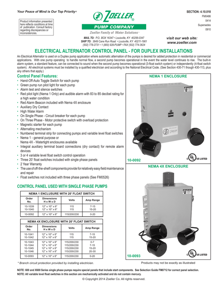
NEMA 1 ENCLOSURE
Hand-Off-Auto Toggle Switch for each pump
Green pump run pilot light for each pump
Alarm test and silence switches
Red pilot light (Nema 1 Only) and audible alarm with 83 to 85 decibel rating for
a high water condition
Red Alarm Beacon included with Nema 4X enclosure
Auxiliary Dry Contact
High Water Alarm
On Single Phase - Circuit breaker for each pump
On Three Phase - Motor protective switch with overload protection
Magnetic starter for each pump
Alternating mechanism
Numbered terminal strip for connecting pumps and variable level float switches
Nema 1 - general purpose or
Nema 4X - Watertight enclosures available
Integral auxiliary terminal board connections (dry contact) for remote alarm
devices
3 or 4 variable level float switch control operation
Three 20’ float switches included with single phase panels
10-0092
2 Year Warranty
The use of off-the-shelf components provide for relatively easy field maintenance
and repair
Float switches not included with three phase panels (See FM0526)
C
UL
US LISTED
UL
US LISTED
R
NEMA 4X ENCLOSURE
CONTROL PANEL USED WITH SINGLE PHASE PUMPS
NEMA 1 ENCLUSURE WITH 20' FLOAT SWITCH
Order
No.
Dimensions
HxWxD
Volts
Amp Range
10-1039
10-1040
12" x 10" x 6"
12" x 10" x 6"
115
115
7-15
15-20
10-0092
12" x 10" x 6"
115/200/230
0-20
NEMA 4X ENCLOSURE WITH 20' FLOAT SWITCH
Order
No.
Dimensions
HxWxD
Volts
Amp Range
10-1041
10-1042
12" x 10" x 6"
12" x 10" x 6"
115
115
7-15
15-20
10-1043
10-1044
10-1045
10-1046
12" x 10" x 6"
12" x 10" x 6"
12" x 10" x 6"
12" x 10" x 6"
115/200/230
115/200/230
115/200/230
115/200/230
0-7
7-15
15-20
20-30
10-0093
12" x 10" x 6"
115/200/230
0-20
* Branch circuit protection provided by installing electrician.
C
10-0093
R
Products may not be exactly as illustrated
NOTE: 600 and X600 Series single phase pumps require special panels that include start components. See Selection Guide FM0712 for correct panel selection.
NOTE: All variable level float switches in this section are mechanically activated and do not contain mercury.
© Copyright 2014 Zoeller Co. All rights reserved.
CONTROL PANEL USED WITH THREE PHASE PUMPS
DUPLEX ELECTRICAL ALTERNATING SYSTEM
NEMA 4X ENCLOSURE (Float Switches not included)
Order
No.
Dimensions
HxWxD
Volts*
Amp Range
10-1102
10-1104
10-1106
10-1108
10-1110
10-1111
10-1112
10-1114
10-1115
10-1183
14" x 12" x 6"
14" x 12" x 6"
14" x 12" x 6"
14" x 12" x 6"
14" x 12" x 6"
14" x 12" x 6"
14" x 12" x 6"
14" x 12" x 6"
14" x 12" x 6"
14" x 12" x 6"
200/230/460
200/230/460
200/230/460
200/230/460
200/230/460
200/230/460
200/230/460
200/230/460
200/230/460
200-208
1.0 - 1.6
1.6 - 2.5
2.5 - 4.0
4.0 - 6.3
6.0 - 10.0
9.0 - 14.0
13.0 - 18.0
17.0 - 23.0
20.0 - 25.0
23.0 - 32.0
10-1154
10-1156
10-1158
14" x 12" x 6"
14" x 12" x 6"
14" x 12" x 6"
575
575
575
1.6 - 2.5
2.5 - 4.0
4.0 - 6.3
*Three phase panel has multi-tap transformer with secondary fusing.
ALARM LIGHT
DISCONNECT
PUMP POWER SUPPLY
CONTROL & ALARM
POWER SUPPLY
(SINGLE PHASE ONLY)
NOTE: ALARM - CONTROL
CIRCUIT SHOULD BE
SEPARATE FROM
PUMP POWER
(SINGLE PHASE ONLY)
ELECTRICAL ALTERNATOR
CONTROL PANEL
NOTE: THREE PHASE PANELS HAVE A
TRANSFOMER WITH SECONDARY FUSING.
INDICATOR LAMPS (INSIDE ENCLOSURE)
TOGGLE SWITCHES (INSIDE ENCLOSURE)
ZOELLER UNICHCEK
CHECK VALVE (2" OR 3")
4 FLOAT SYSTEM
ALARM BELL "ON"
BOTH PUMPS ALREADY
ACTIVATED SET ABOVE OVERRIDE
AND BELOW INLET
2" OR 3" DISCHARGE PIPE
FLOOR FLANGE
4" HUB INLET
ZOELLER FIBERGLASS
OR POLYETHYLENE
BASIN
"ALARM-OVERRIDE LEVEL SET
ABOVE "ON" FLOAT AND
BELOW INLET BOTH PUMPS
"ON" ALARM BELL "ON"
3 FLOAT SYSTEM
ZOELLER FLOAT SWITCH
ZOELLER SEWAGE PUMP
5"
"ON" LEVEL PUMPS ALTERNATE
OPERATION EACH CYCLE MAXIMIZE
BASED ON DEPTH AND VOLUME
OF BASIN
MINIMUM "OFF" LEVEL
Sequence of Operation for Duplex Panel
1.
2.
Operation can begin after the following:
- Correct voltage is supplied to Panel
- Panel is properly grounded
- Pumps are connected correctly to Panel
- Panel Circuit Breakers are closed
- Floats are installed properly
- Overload Protection is adjusted to Pump nameplate amps
- Pump HOA Switches are set to “Auto”
- Control On/Off Switch is set to “On”
When the “Stop” and “Lead” floats are closed Pump 1 will energize
and the Pump 1 Pump Run Light will illuminate. Pump 1 will remain
operational until the “Stop” float opens.
3. The next time the “Stop” and “Lead” floats are closed the Alternating
Circuit will energize Pump 2 and the Pump 2 Pump Run Light will
illuminate. Pump 2 will remain operational until the “Stop” float opens.
This cycle will repeat each time the fluid level rises and falls.
4. If the fluid level continues to rise after the first pump has been energized the “Lag” float will close. When the “Lag” float has closed the
second Pump will Energize. Both Pumps will remain operational until
the “Stop” float opens.
SK289
5. In a three float system when the “Lag” float is closed the following will
also occur:
- The External High Water Light will illuminate
- The Audible High Water Horn will sound
- The Auxiliary Dry Contacts will close
6. In a four float system, the alarm float should be the third float causing
an alarm to sound when the lead pump fails to operate or the rate of
in flow into the basin exceeds the capacity of one pump. When the
alarm float is closed the following will occur.
- The External High Water Light will illuminate
- The Audible High Water Alarm will sound
- The Auxiliary Dry Contacts will close
As the liquid level continues to rise the fourth float will close, energizing
the lag pump. The lag pump and the lead pump will remain energized
until the "Stop" float opens.
NOTE: In Duplex systems where it is considered normal for two pumps
to operate in tandem during peak flow conditions, the third and fourth
float may be reversed.
7. The Audible High Water Horn can be silenced by pressing the Alarm
Silence Button. When the “Alarm” float opens the External High
Water Light, Audible High Water Horn and Dry Auxiliary Contacts will
be reset.
All electrical systems must be installed by a qualified licensed electrician and according to the National Electrical
Code. (See section 430-71 through 430-113 plus any others that apply)
Refer to FM0712 for correct selection of Electrical Alternator.
© Copyright 2014 Zoeller Co. All rights reserved.


