A model for circuits part 2: Potential difference
advertisement

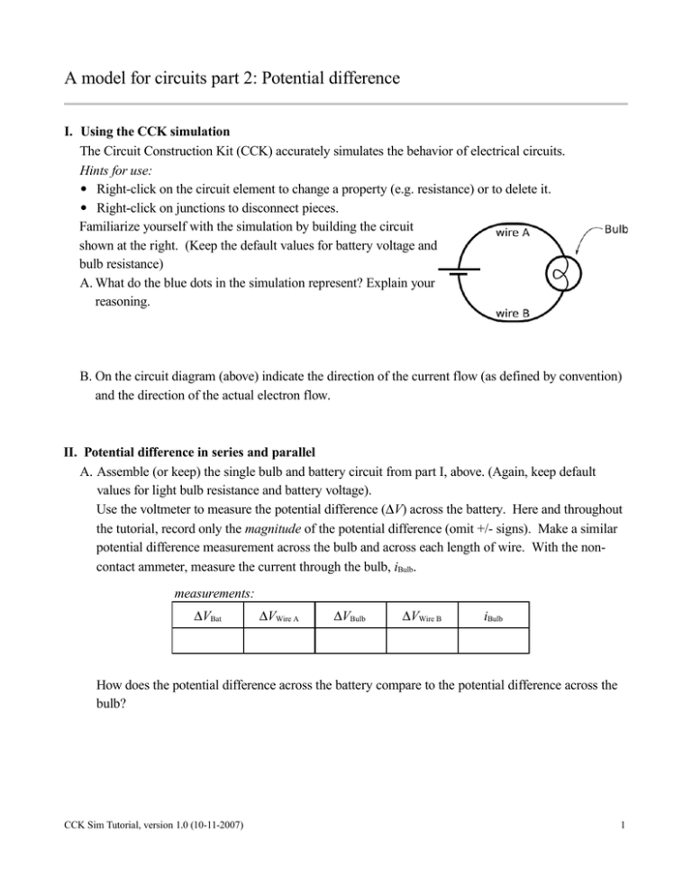
A model for circuits part 2: Potential difference I. Using the CCK simulation The Circuit Construction Kit (CCK) accurately simulates the behavior of electrical circuits. Hints for use: Right-click on the circuit element to change a property (e.g. resistance) or to delete it. Right-click on junctions to disconnect pieces. Familiarize yourself with the simulation by building the circuit shown at the right. (Keep the default values for battery voltage and bulb resistance) A. What do the blue dots in the simulation represent? Explain your reasoning. B. On the circuit diagram (above) indicate the direction of the current flow (as defined by convention) and the direction of the actual electron flow. II. Potential difference in series and parallel A. Assemble (or keep) the single bulb and battery circuit from part I, above. (Again, keep default values for light bulb resistance and battery voltage). Use the voltmeter to measure the potential difference (V) across the battery. Here and throughout the tutorial, record only the magnitude of the potential difference (omit +/- signs). Make a similar potential difference measurement across the bulb and across each length of wire. With the noncontact ammeter, measure the current through the bulb, iBulb. measurements: VBat VWire A VBulb VWire B iBulb How does the potential difference across the battery compare to the potential difference across the bulb? CCK Sim Tutorial, version 1.0 (10-11-2007) 1 B. Set up the circuit containing two bulbs in series as shown (again using default values for bulb resistance and battery voltage). 1. Before making any measurements, rank from largest to smallest the currents through bulb 1, bulb 2, and the bulb in the single-bulb circuit from part A (iBulb 1, iBulb 2, isingle). Also rank the bulbs brightness from brightest to dimmest. Explain your reasoning. 2. Measure the potential difference across each element, and complete the table at the right. measurements: VBat VBulb 1 VBulb 2 3. Given these measurements, consider what would happen if the resistance of bulb 2 (R2) were decreased. Completing the following tables, predict whether the following quantities would increase (↗), decrease (↘), or stay the same (−), as R2 is decreased. Predict what happens to the current through the battery and the potential difference across the battery as R2 decreases. Given this prediction, predict what happens to the current through bulb 1, the potential difference across bulb 1, and the brightness of bulb 1 as R2 decreases. predictions: iBat VBat predictions: iBulb 1 VBulb 1 Given this prediction, predict what happens to the current through predictions: bulb 2 and the potential difference across bulb 2 as R2 decreases. iBulb 2 Explain your reasoning. brightness 1 VBulb 2 After R2 has been reduced, complete the following comparisons with the symbols <, >, = iBulb 1_______ iBulb 2 VBulb 1____VBulb 2 After R2 has been increased, how do you expect the brightness of bulb 2 to compare to that of bulb 1? CCK Sim Tutorial, version 1.0 (10-11-2007) 2 4. Now check all your predictions in the simulation using the voltmeter and ammeter, completing the table below. Note that a bulb's resistance may be changed by right-clicking on it and changing the resistance with the slider. When R2 decreases (use the symbols ↗,↘ and −)... measurements: iBat VBat iBulb 1 VBulb 1 brightness 1 iBulb 2 VBulb 2 brightness of 2 relative to 1 If any measurement results were different from what you predicted, discuss them here. How can you make sense of any surprises? 5. Measure the potential difference across each circuit measurements: element (battery and bulbs). Considering your VBat VBulb 1 measurements (here and in question II.B.2), construct a mathematical relationship between VBulb 1, VBulb 2, and VBat that holds true in general for this circuit. VBulb 2 And another relationship that holds true for iBat, iBulb 1 and iBulb 2 (use the non-contact ammeter to inspect the circuit currents). C. Set up the circuit with two bulbs in parallel, as shown. Make sure you start with new bulbs (10 each). 1. Before making any measurements, rank from largest to smallest the currents through bulb 1, bulb 2, and the bulb in the single-bulb circuit from part A (iBulb 1, iBulb 2, isingle). Also rank the bulbs brightness from brightest to dimmest. Explain your reasoning. CCK Sim Tutorial, version 1.0 (10-11-2007) 3 2. Measure the potential difference across each element, and complete the table at the right. measurements: VBat VBulb 1 VBulb 2 3. Given these measurements, consider what would happen if R2 (the resistance of bulb 2) were increased. Completing the following tables, predict whether the following quantities would increase (↗), decrease (↘), or stay the same (−), as R2 is increased. Predict what happens to the current through the battery and the potential difference across the battery as R2 increases. Predict what happens to the current through bulb 1, the potential difference across bulb 1, and the brightness of bulb 1 as R2 increases. predictions: iBat VBat predictions: VBulb 1 iBulb 1 Predict what happens to the current through bulb 2 and the potential difference across bulb 2 as R2 increases. Explain your reasoning. brightness 1 predictions: iBulb 2 VBulb 2 After R2 has been increased, complete the following comparisons with the symbols <, >, = iBulb 1_______ iBulb 2 VBulb 1____VBulb 2 After R2 has been increased, how do you expect the brightness of bulb 2 to compare to that of bulb 1? 4. Now check all your predictions in the simulation using the voltmeter and ammeter, completing the table below. Note that a bulb's resistance may be changed by right-clicking on it and changing the resistance with the slider. When R2 increases (use the symbols ↗,↘ and −)... measurements: iBat VBat iBulb 1 VBulb 1 brightness 1 iBulb 2 VBulb 2 brightness of 2 relative to 1 If any measurement results were different from what you predicted, discuss them here. How can you make sense of any surprises? CCK Sim Tutorial, version 1.0 (10-11-2007) 4 5. Measure the potential difference across each circuit measurements: element (battery and bulbs). Construct a general VBat VBulb 1 mathematical relationship between VBulb 1, VBulb 2, and VBat for this circuit (consider also your answer to question II.C.2). VBulb 2 Construct a general mathematical relationship that holds true for iBat, iBulb 1 and iBulb 2 for this circuit (use the non-contact ammeter to inspect the currents). D. Answer the following questions based on all the circuits you have considered so far. You may also experiment with any additional circuits you would like to try. (For this problem, the bulbs here are fixed at constant resistance). 1. Is it possible to change the potential difference across a real light bulb without also changing the current through it? (As in real life, you're not able to change the resistance of the bulb.) Explain. 2. Is it possible to change the current through a real light bulb without changing the potential difference across it? Explain. 3. Consider how changes in current through and potential difference across a light bulb relate to changes its brightness. Circle the correct answer: If a light bulb becomes brighter, the current through it has... (increased, decreased, stayed the same, can't know for sure). If a light bulb becomes brighter, the potential difference across it has... (increased, decreased, stayed the same, can't know for sure). Check your answer with a tutorial instructor. CCK Sim Tutorial, version 1.0 (10-11-2007) 5 III. Extending the model Our model for electric circuits includes the idea that, for identical bulbs, the brightness of a bulb is an indicator of the current through the bulb. Based on our observations in this tutorial, we can extend the model to include the idea that, for circuits containing identical bulbs, the brightness of a bulb is also and indicator of the potential difference across the bulb. A. Set up the circuit with three 10 bulbs, as shown, and observe the brightness. 1. Before making the voltmeter measurements, predict the ranking of the potential difference across the battery and each bulb ( VBat, V1, V2, and V3). Explain your reasoning. 2. Measure the potential difference across measurements: VBat VBulb 1 each element in the circuit. If your measurements are not consistent with the ranking above, revise your reasoning here. VBulb 2 VBulb 3 3. How is this circuit similar to the series circuit studied in part II.B? (Hint: think about how bulbs 2 and 3 together could be replaced by a single bulb.) CCK Sim Tutorial, version 1.0 (10-11-2007) 6 B. Before setting up the circuit shown at the right: 1. Predict the ranking of the currents through the battery and each bulb (iBat, i1, i2, and i3). Explain. 2. Predict the voltmeter measurements predictions: across each of the elements in the circuit VBat shown. Explain. 3. Set up the circuit and check your predictions. If your observations and measurements are not consistent with your predictions, explain the inconsistencies. CCK Sim Tutorial, version 1.0 (10-11-2007) VBulb 1 VBulb 2 VBulb 3 VBulb 1 VBulb 2 VBulb 3 measurements: VBat 7 C. Both circuits at the right have more than one path for the current. Sketch all possible current loops on the diagrams. (A "current loop" is a single path of conductors that connects one side of the battery to the other.) For each of the current loops you have drawn, calculate the sum of the potential differences across the bulbs in that loop. (Use the measurements you made above.) How do the sums of the potential differences across the bulbs in each loop compare to the potential difference across the battery? Check your answer with a tutorial instructor. CCK Sim Tutorial, version 1.0 (10-11-2007) 8 IV. Exploring resistive wires Construct the simple circuit from part I again, shown here. Under the Advanced control panel, increase the Wire Resistivity to some higher value. While keeping the red probe of the voltmeter at the positive battery terminal, slowly move the black probe away from the red probe toward the bulb, and continue around the circuit. Describe how the potential difference between the probes changes as the black probe is scanned along the entire circuit. Compare this behavior to that of the circuit with no resistance in the wires. CCK Sim Tutorial, version 1.0 (10-11-2007) 9


