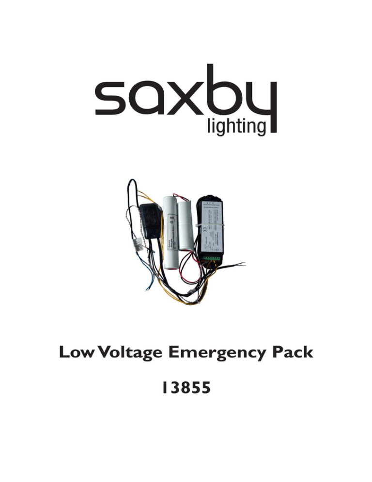
Low Voltage Emergency Pack 13855
advertisement

Low Voltage Emergency Pack 13855 Thank you for purchasing this accessory. Please read the instructions carefully before use to ensure safe and satisfactory operation of this accessory. Please retain these instructions for future reference. Warning This is a Class 1 product and must be earthed. Live Voltages may be present in this unit even when turned of or when completely disconnected. Please read these instructions carefully before commencing any work. This unit must be fitted by a competent and qualified electrician. Install in accordance with IEE Wiring regulations and current Building Regulations. To prevent electrocution switch off at mains supply before installing or maintaining this fitting. Ensure other persons cannot restore the electrical supply without your knowledge. This light fitting should be connected to a fused circuit. If replacing an existing fitting, make a careful note of the connections. This system contains non-replaceable parts and cannot be serviced. If damage occurs the part should be scrapped. This product is not suitable for dimming. Waste electrical products should not be disposed of with household waste. Please recycle where facilities exist. Check with your local authority or retailer for recycling advice. These products should not be fitted to PIR circuits or short duration timed switches. This unit is for emergency lighting use only. The unit has a a minimum rating of 35W and a maximum of 50W. All switching etc. must comply with BS5266 part 1 and the latest edition of the I.E.E. Wiring Regulations. This unit requires an unswitched 230 - 240V mains supply to charge the battery and monitor the mains for failure. Ensure that ALL electrical connections are tight with no loose strands, including factory connections. Preparation 1. The battery must be connected before installation. Connect the red wire from the battery into the terminal marked ‘RED +’ on the Conversion Unit. 2. Feed the assembly carefully into the long fireproof bag. Batteries first, followed by the conversion unit and finally the low voltage transformer. Ensure that the two mains cables, the low voltage output and the LED indicator extend out the end of the bag, and secure with a cable tie. 3. Cable ties should be tied around the long fireproof bag long fireproof bag to hold each component of the train firmly in place. 4. The end of the assembly should be tied close to the transformer in order to leave sufficient cable length for connection to the mains supply, downlight and to allow the LED indicator to be fixed in position. 5. The Low Voltage Emergency Pack is now ready for installation. Battery Battery Converter Transformer Installation 6. 7. Cut the downlight cut-out hole in the required position. For cut-out size refer to the installation instructions or packaging of the selected downlight. A correctly packed LV emergency pack should fit through a 73mm diameter hole. Insert the Low Voltage Emergency Pack through the downlight cut-out in the ceiling. Wiring Non-Maintained Wiring (Light Off Continuous): 8. Position the Low Voltage Emergency Pack away from the downlight and ensure that it is not covered by insulation or any other material. The Low Voltage Emergency Pack must be at least 75mm from the edge of the downlight. Ensure that all the cables are well away from the downlight. 9. Connect the unswitched permanent live feed to the three core cable marked ‘Unswitched Permanent Supply’. 10. For non-maintained operation do not connect the two core cable marked ‘Maintained Emergency’. Wrap the live and neutral in two layers of insulation tape. 11. To fit the charge indicator LED, drill a 5mm hole at a minimum distance of 25mm from the downlight to be used. Remove the black surround from the LED and push in from the ceiling side. Gently push the LED into the hole from the ceiling void until the tip is visible from beneath. 12. Connect the lamp output wires marked ‘Output to 12V’ to the lampholder on the downlight. Insert the lamp into the lamp holder and fit into the downlight. Transformer Input A B 1 2 12V - UNSWITCHED PERMANENT SUPPLY LAMP EARTH (GREEN/YELLOW) E PERMANANT LIVE L NEUTRAL N L Low Voltage Lamp + PINK -a GREY -c LED Indicator Battery SWITCHED SUPPLY (ISOLATE) N SELV Transformer RED BLACK - + - LED + - Battery Maintained Wiring: 13. Position the Low Voltage Emergency Pack away from the downlight and ensure that it is not covered by insulation or any other material. The Low Voltage Emergency Pack must be at least 75mm from the edge of the downlight. Ensure that all the cables are well away from the downlight. 14. Connect the unswitched permanent live feed to the three core cable marked ‘Unswitched Permanent Supply’. 15. Connect the switched mains supply to the two core cable marked ‘Maintained Emergency’, ‘blue wire’ to the neutral and the ‘brown wire’ to the switched live. 16. To fit the charge indicator LED, drill a 5mm hole at a minimum distance of 25mm from the downlight to be used. Remove the black surround from the LED and push in from the ceiling side. Gently push the LED into the hole from the ceiling void until the tip is visible from beneath. 17. Connect the lamp output wires marked ‘Output to 12V’ to the lampholder on the downlight. Insert the lamp into the lamp holder and fit into the downlight. 18. Install the downlight into the ceiling. 19. The downlight can be switched as normal in a maintained condition from the light switch. SWITCHED SUPPLY SWITCHED LIVE Transformer NEUTRAL Input A B 1 12V - UNSWITCHED PERMANENT SUPPLY LAMP N SELV Transformer L Low Voltage Lamp SWITCHED LIVE EARTH (GREEN/YELLOW) E PERMANANT LIVE L NEUTRAL N Check That You have correctly identified the wires. The connections are tight. No loose strands have been left out of the connection block. LED Indicator Battery + PINK -a GREY -c RED BLACK + - LED + - Battery Testing After connecting the permanent as well as the switched supply (if required) mains supply check the following: 20. The LED is illuminated. This indicates that the permanent mains supply is present and that the charger circuit is working correctly. 21. The lamp will light under emergency conditions, by removing the unswitched mains supply. 22. The lamp will light in maintained condition by switching the switched supply. 23. The unit should be left on charge for a minimum of 24 hours before testing. Once this unit is charged it must be connected at all times 24. To simulate normal mains supply failure, isolate the unswitched mains supply to the fitting, or use test switches if installed. When the unit no longer meets its rated duration of operation the battery pack must be replaced with a battery of the same type, voltage and Amp-hour rating. Recycling Advice Waste electrical products should not be disposed of with household waste. Please recycle where facilities exist. Check with your Local Authority or retailer for recycling advice. Safety Information Live Voltages may be present in this unit even when turned of or when completely disconnected. For your safety, always switch off the supply before changing lightbulbs, or cleaning. This system contains non-replaceable parts and cannot be serviced. If damage occurs the part should be scrapped. Saxby Lighting Ltd. BH23 3PE 111010


