Electrically auto-tuned RF coil design
advertisement

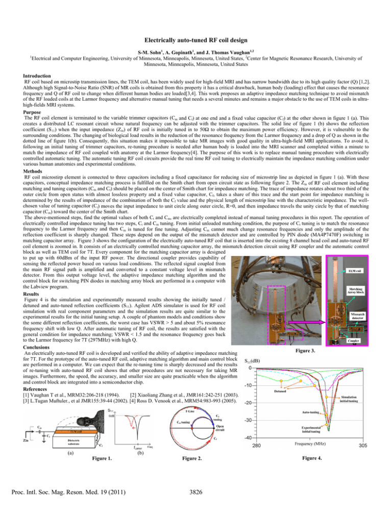
Electrically auto-tuned RF coil design 1 S-M. Sohn1, A. Gopinath1, and J. Thomas Vaughan1,2 Electrical and Computer Engineering, University of Minnesota, Minneapolis, Minnesota, United States, 2Center for Magnetic Resonance Research, University of Minnesota, Minneapolis, Minnesota, United States Introduction RF coil based on microstip transmission lines, the TEM coil, has been widely used for high-field MRI and has narrow bandwidth due to its high quality factor (Q) [1,2]. Although high Signal-to-Noise Ratio (SNR) of MR coils is obtained from this property it has a critical drawback, human body (loading) effect that causes the resonance frequency and Q of RF coil to change when different human bodies are loaded[3,4]. This work proposes an adaptive impedance matching technique to avoid mismatch of the RF loaded coils at the Larmor frequency and alternative manual tuning that needs a several minutes and remains a major obstacle to the use of TEM coils in ultrahigh-fields MRI systems. Purpose The RF coil element is terminated to the variable trimmer capacitors (Cm and Ct) at one end and a fixed value capacitor (Cf) at the other shown in figure 1 (a). This creates a distributed LC resonant circuit whose natural frequency can be adjusted with the trimmer capacitors. The solid line of figure 1 (b) shows the reflection coefficient (S11) when the input impedance (Zin) of RF coil is initially tuned in to 50Ω to obtain the maximum power efficiency. However, it is vulnerable to the surrounding conditions. The changing of biological load results in the reduction of the resonance frequency from the Larmor frequency and a drop of Q as shown in the dotted line of figure 1(b). Consequently, this situation makes it impossible to take MR images with good quality in ultra-high-field MRI applications. To avoid it, following an initial tuning of trimmer capacitors, re-tuning procedure is needed after human body is loaded into the MRI scanner and completed within a minute to match the impedance of RF coil coupled with anatomy at the Larmor frequency[4]. The purpose of this work is to replace manual tuning procedure with electrically controlled automatic tuning. The automatic tuning RF coil circuits provide the real time RF coil tuning to electrically maintain the impedance matching condition under various human anatomies and experimental conditions. Methods RF coil microstirp element is connected to three capacitors including a fixed capacitance for reducing size of microstrip line as depicted in figure 1 (a). With these capacitors, conceptual impedance matching process is fulfilled on the Smith chart from open circuit state as following figure 2. The Zin of RF coil element including matching and tuning capacitors (Cm and Ct) should be placed on the center of Smith chart for impedance matching. The trace of impedance rotates about two third of the outer circle from open status with almost lossless property and a fixed value capacitor, Cf, takes a share of this trace and the start point for impedance matching is determined by the results of impedance of the combination of both the Cf value and the physical length of microstrip line with the characteristic impedance. The wellchosen value of tuning capacitor (Ct) moves the input impedance to unit circle along outer circle, R=0, and then impedance travels the unity circle by that of matching capacitor (Cm) toward the center of the Smith chart. The above-mentioned steps, find the optimal values of both Ct and Cm, are electrically completed instead of manual tuning procedures in this report. The operation of electrically controlled impedance tuning has two steps, Ct and Cm tuning. From initial unloaded matching condition, the purpose of Ct tuning is to match the resonance frequency to the Larmor frequency and then Cm is tuned for fine tuning. Adjusting Cm cannot much change resonance frequencies and only the amplitude of the reflection coefficient is sharply changed. These steps depend on the output of the mismatch detector and are controlled by PIN diode (MA4P7470F) switching in matching capacitor array. Figure 3 shows the configuration of the electrically auto-tuned RF coil that is inserted into the existing 8 channel head coil and auto-tuned RF coil element is zoomed in. It consists of an electrically controlled matching capacitor array, the mismatch detection circuit using RF coupler and the automatic control block as well as TEM coil for 7T. Every component for the matching capacitor array is designed to put up with 60dBm of the input RF power. The directional coupler provides capability of sensing the reflected power based on various load conditions. The reflected signal coupled from the main RF signal path is amplified and converted to a constant voltage level in mismatch detector. From this output voltage level, the adaptive impedance matching algorithm and the control block for switching PIN diodes in matching array block are performed in a computer with the Labview program. Results Figure 4 is the simulation and experimentally measured results showing the initially tuned / detuned and auto-tuned reflection coefficients (S11). Agilent ADS simulator is used for RF coil simulation with real component parameters and the simulation results are quite similar to the experimental results for the initial tuning setup. A couple of phantom models and conditions show the some different reflection coefficients, the worst case has VSWR > 5 and about 5% resonance frequency shift with low Q. After automatic tuning of RF coil, the results are satisfied with the general condition for impedance matching; VSWR < 1.5 and the resonance frequency goes back to the Larmor frequency for 7T (297MHz) with high Q. Conclusions Figure 3. An electrically auto-tuned RF coil is developed and verified the ability of adaptive impedance matching for 7T. For the prototype of the auto-tuned RF coil, adaptive matching algorithm and main control block are performed in a computer. We can expect that the re-tuning time is sharply decreased and the results of re-tuning with auto-tuned RF coil shows that other procedures are not necessary for taking MR images. Furthermore, the speed, the accuracy, and smaller size are quite practicable when the algorithm and control block are integrated into a semiconductor chip. References [1] Vaughan T et al., MRM32:206-218 (1994). [2] Xiaoliang Zhang et al., JMR161:242-251 (2003). [3] L.Tugan Muftuler., et al JMR155:39-44 (2002). [4] Ross D. Venook et al., MRM54:983-993 (2005). (a) (b) Figure 1. Proc. Intl. Soc. Mag. Reson. Med. 19 (2011) Figure 2. 3826 Figure 4.
