ESL-IE-83-04-111
advertisement

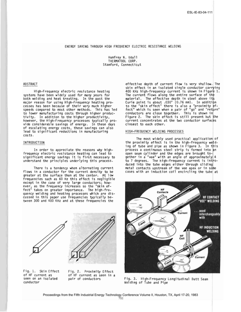
ESL-IE-83-04-111 ENERGY SAVING THROUGH HIGH FREQUENCY ELECTRIC RESISTANCE WELDING Humfrey N. Udall THERMATOOL CORP. Stamford, Connecticut ABSTRACT High-Frequency electric resistance heating systems have been widely used for many years for both welding and heat treating. In the past the major reason for using High-Frequency heating pro­ cesses has been because of their very much higher speeds compared to most other methods. This has led to lower manufacturing costs through higher produc­ tivity. In addition to the higher productivity, however, the High-Frequency processes typically pro­ vide considerable saVings of energy. In these days of escalating energy costs, these savings can also lead to significant reductions in manufacturing cos ts. INTRODUCTION In order to appreciate the reasons why high­ frequency electric resistance heating can lead to significant energy savings it is first necessary to understand the principles underlying this process. There is a tendency when alternating current flows in a conductor for the current density to be greater at the surface than at the center. At low frequencies such as 60 Hz this effect is negligible except in the case of very large conductors; how­ ever, as the frequency increases so the "skin ef­ fect" takes on greater importance. The high-fre­ quency welding and heating processes which are dis­ cussed in this paper use frequencies typically be­ tween 300 and 400 KHz and at these frequencies the Fig. 1. Skin Effect of HF current as seen on an isolated conductor Fig. 2. Proximity Effect of HF current as seen in a pair of conductors effective depth of current flow is very shallow. The skin effect in an isolated single conductor carr~ing 400 KHz high-frequency current is shown in Figur 1. The current flows along the entire surface of th material. The effective depth in steel above itl Curie point is about .030" (0.76 mm). In additi n to the "skin effect" there is also a "proximity f­ fect" Which is seen when a pair of "go" and "ret rn" conductors are close together. This is shown in Figure 2. The skin effect is still present but he current concentrates at the two conductor surfac s closest to each other. HIGH-FREQUENCY WELDING PROCESSES The most wi dely used practical appl ication the prOXimity effect is in the high-frequency we ing of tube and pipe as shown in Figure 3. In t process a continuous steel strip is formed into open seam cylinder and the edges are brought to­ gether in a "vee" with an angle of approximately to 7 degrees. The high-frequency current is int duced into the tube edges either through sliding metal contacts upstream of the vee apex or in so cases with an induction coil encircling the tube Fig. 3. High-Frequency Longitudinal Butt Seam Welding of Tube and Pipe Proceedings from the Fifth Industrial Energy Technology Conference Volume II, Houston, TX, April 17-20, 1983 701 of d­ is n 4 0­ e at ESL-IE-83-04-111 th i s poi nt. Here the "go" and "return" conductors are the tube edges themselves. This is an almost ideal example of the skin effect and the proximity effect which together confine the heating currents to the edges of the tube to be welded allowing them to be heated to welding temperature at a high rate of speed and forge welded together at the weld point by the squeeze roll assembly. The resultant weld has an extremely narrow heat affected zone and hence requires a very small heat input compared either to low frequency electric resistance welding or to arc welding processes. Figure 4 is a graph which shows the power cost savings for high-frequency welding compared to low frequency electric resistance weld­ ing. Table 1 gives a comparison between typical speeds and power inputs for longitudinal seam weld­ ing by both the high-frequency resistance process and conventional arc welding processes. Power Cost Savings HF Contact vs. ERW Welding (Based on $.04/KWH Rate) -:- 30 THERMATOOL Welders ~ VT-80 • VT-160 a: J: en 25 a: :5-I 20 o e, 15 en Tubes are welded on production mills at diame­ ters which may range from 0.4" (10 mm) on small tube mills to 48" (1220 mm) on large pipe mills. Wall thickness can range from 0.003" (0.08 mm) to 1.0" (25 mm). Typical welding speeds are from 500 ft/min (150 m/m) to 50 ft/min (15 m/m) and the capacity of the welders used is from 30 KW to 600 KW. In addi­ tion to the power cost savings considerably higher productivity is realized because of the higher weld­ ing speeds which can be obtained using the high-fre­ quency process. ~ 10 en 5 ~ .080" .120" .160" .200" 2.0mm 3.0mm 4.0mm 5.1mm The advantages of high-frequency welding are not limited to the longitudinal seam welding of tube and pipe. Many other industrial products are pro­ duced using modifications of the basic process. Among these are fins spirally welded to tubes for use in heat exchangers'and the economizer sections of steam boilers, fins longitudinallY welded to tube for the manufacture of boiler water walls, tubes longitudinally welded to sheets for freezer liners and solar absorber plates, spirally welded corru­ gated culvert and spirally welded piling, longitu­ dinally welded roll formed sections for the trans­ portation industry, longitudinally welded "I" and "H" beams for truck trail er frames, mobil'e home frames and general light structual uses and cable she~thing which is continuously welded around the cable core. Some of these applications are illus­ trated in Figure 5. Fig. 4. Although the majority of high-frequency weld­ ing applications are for carbon, alloy and stainless steels, a wide variety of non-ferrous materials are also welded. These include copper, brass, cupro­ nickel and other copper alloys, aluminum and alumi­ num alloys, titanium and zirconium. Dissimilar met­ als can also be high-frequency welded such as carbon steel to stainless steel for automotive trim and copper tubes to aluminum strips for solar absorber plates. Dual wall tubes can also be longitudinally seam welded from two separate strips of material for automotive and transportation applications. The two walls may both be of carbon steel to provide a sound deadening effect or one wall m~ be of stainless steel and the other of carbon steel to provide in­ creased corrosion resistance at minimum cost. WALL THICKNESS TABLE I POWER SAVINGS H.F. WELDING VS. ARC WELDING (CARBON STEEL) PROCESS THICKNESS ARC INCHES VOLTS ARC POWER AMPS KW FCAW 0.125 325 HFRW 0.125 FCAW 0.25 28 475 SAW 0.25 33 900 HFRW 0.25 SAW 0.50 HFRW 0.50 28 200 4.6 13,200 2.1 13.3 125 10.6 29.7 130 22.8 11 ,820 4.7 90 41.6 8,400 13.2 9.1 275* 555* 34 1100 SPEED POWER FT /HR KWH PER 100 FT 37.4 1100* Data for arc welding is from Welding Handbook Seventh Edition, Volume 2 pages 177, 179, and 210. Data for H. F. Welding is from THERMATOOL CORP. NOTE:- Input power requirements for 160 KW, 300 KW and 600 KW welder output capacities respectively. Proceedings from the Fifth Industrial Energy Technology Conference Volume II, Houston, TX, April 17-20, 1983 702 ESL-IE-83-04-111 Fig. 5. Examples of some of the varied products made using the High-Frequency Resistance or Induction welding processes. HIGH-FREQUENCY SELECTIVE SURFACE HARDENING The same basic high-frequency principles of "skin effect" and "proximity effect" can be applied to the selective surface hardening of steels. This process also has significant potential for saving energy since in many cases a workpiece will be com­ pletely hardened when only a small hardened area is actually needed to resist local wear. The basic arrangement of such a system is shown in Figure 6. In this case the "go" current runs between two con­ tacts on the workpiece and the "return" current runs in a proximity conductor which is postioned close to the workpiece and whose shape defines the shape of the current path in the workpiece. Figure 7 is a cross section showing the relationship of the HF current pattern to the proximity conductor. In ad­ dition to saving energy this process also leads to very high productivity since in all cases the hard­ ening cycle is completed in less than one second. Heating times of 0.2 to 0.5 second are typical and the process is applicable to most grades of carbon steel. hardenable cast irons, and many powder metal compositions. Lines up to 40" (l020 mml long x 0.1" (2.5 mml wide have been hardened as well as lines up to 0.75" (19 mml wide x 4" (l00 mml long. Figure 8 CURRENT--I7~__~2 HF A CONTACT Fig. 6. High Frequency Selective Surface Hardenlng - Gasic Arrangement PROXIMITY CONDUCTOR HF CURRENT PATTERN SECTION A-A Fig. 7. Cross Sectional View of Fig. 6. Proceedings from the Fifth Industrial Energy Technology Conference Volume II, Houston, TX, April 17-20, 1983 703 ESL-IE-83-04-111 Fig. 8. Pipe wrench jaw with cross section showing HF selective hardening on tooth tips. Fig. 9. Cross section cut from an automotive part with a higher magnification photograph of one of the six HF selective surface hardened wear faces. shows the jaw of a pipe wrench and a cross section of the serrations which have been selectively hard­ ened at the tips. Figure 9 shows a cross section of an automotive component which has been internally hardened in six places together with a higher magni­ fication photograph of one of the selectively hard­ ened areas. The process is applicable to many parts used in the automotive, appliance and consumer products industries. CONCLUSIONS In summary high frequency welding and selec­ tive surface heating can be used in many high pro­ duction processes both to improve productivity and to save energy, with a resulting decrease in manu­ facturing costs. Proceedings from the Fifth Industrial Energy Technology Conference Volume II, Houston, TX, April 17-20, 1983 7~

