elite® series - Refrigeracion Lozano
advertisement
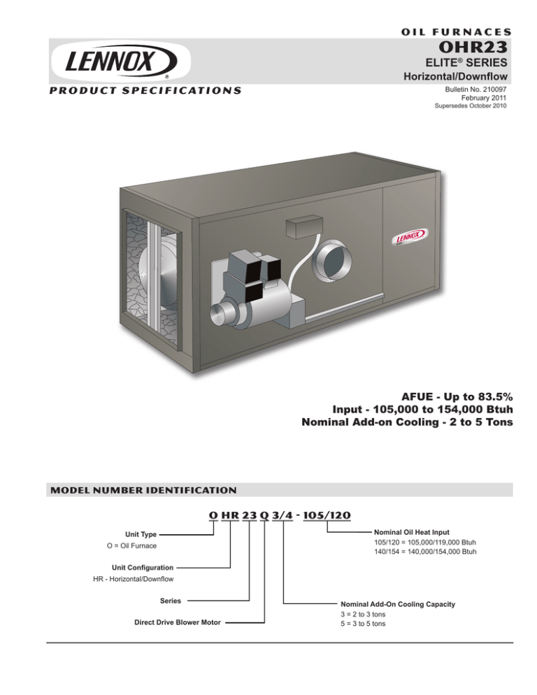
OIL FURNACES OHR23 ELITE® SERIES Horizontal/Downflow P R O D U C T S P E C I F I C AT I O N S Bulletin No. 210097 February 2011 Supersedes October 2010 AFUE - Up to 83.5% Input - 105,000 to 154,000 Btuh Nominal Add-on Cooling - 2 to 5 Tons MODEL NUMBER IDENTIFICATION O HR 23 Q 3/4 - 105/120 Nominal Oil Heat Input 105/120 = 105,000/119,000 Btuh 140/154 = 140,000/154,000 Btuh Unit Type O = Oil Furnace Unit Configuration HR - Horizontal/Downflow Series Direct Drive Blower Motor Nominal Add-On Cooling Capacity 3 = 2 to 3 tons 5 = 3 to 5 tons FEATURES Contents Accessory Dimensions . . . . . . . . . 7 Blower Data . . . . . . . . . . . . . . 5 C Dimensions . . . . . . . . . . . . . . . 6 Features . . . . . . . . . . . . . . . . 2 Installation Clearances . . . . . . . . . 4 Model Number Identification . . . . . . 1 Optional Accessories . . . . . . . . . . 4 Specifications . . . . . . . . . . . . . . 4 Equipment Warranty Heat exchanger - limited lifetime warranty in residential applications, twenty years in non-residential applications. Oil burner and all other covered components limited five year warranty in residential applications, one year in non-residential applications. Refer to the Lennox Equipment Limited Warranty certificate included with the equipment for details. APPROVALS Units have been rated and tested according to U.S. Department of Energy (DOE) test procedures and Federal Trade Commission (FTC) labeling regulations. Units are certified by AHRI. Units are ETL/Intertek listed. Developed in accordance with ISO 9001 quality standards. APPLICATIONS Designed to be installed in either horizontal or downflow position. Designed for reduced clearances to combustibles. Optional additive floor base is available for installation in the downflow position on combustible floors. Units can be installed on a slab or suspended in a crawl space, basement, utility room or furnace room. Units are not approved for attic installations. Lennox add-on indoor coil, remote air conditioner, powered air cleaner and humidifier can easily be added to the furnace. Each unit is completely factory assembled with all controls installed and wired. HEATING SYSTEM B Beckett Flame-Retention Oil Burner Smooth operating, high-pressure atomizing type burner blends oil and air to attain maximum efficiency. Heavy duty motor drives quiet operating blower wheel and fuel pump. Air turbo injector directs combustion air for smooth ignition. OHR23 / Page 2 D B E Flame retention head is designed to agitate and mix oil and air for complete combustion and highest efficiency. Burner design features 4 in. connection to air inlet for optional outdoor combustion air. Oil pump located on opposite side of air inlet to prevent any dirt accumulation from inlet air. Burner has 14,000 volt ignition transformer and ceramic glazed electrodes which provide a safe continuous flame. Equipped with a factory installed cadmium sulfide cell flame detector and primary safety control that provides complete shutdown in case of flame failure. All burner parts are easily removable for servicing. Burner is U.L. approved, C.S.A. certified and certified according to ANSI Standard 296.6. Burner is factory installed in the unit, wired and fire tested. Units are shipped for lower heating capacity operation. Nozzle must be field provided for field conversion to higher heating capacity. C EZ Clean Heat Exchanger Streamlined drum type heat exchanger exposes maximum surface area to the air stream with minimum air resistance. Constructed of heavy gauge steel for maximum service life. Strategically placed ports allow easy cleaning. Heavy gauge mounting channels are provided in cabinet base for support of heat exchanger. Combustion Chamber All models have a factory installed, specially designed alumina silica ceramic fiber combustion chamber. Combustion chamber can withstand temperatures of up to 2550°F resulting in more complete combustion and higher efficiencies. Flame Inspection Tube Conveniently located at the front of the unit. Opening is large enough for normal inspection mirror. FEATURES HEATING SYSTEM (CONTINUED) OPTIONS .Oil Filter Recommended for proper oil filtration. See Specifications table for order number. Two Stage Oil Pump Two stage oil pump is available. See Specifications table for order number. CONTROLS Electronic Fan Timer Control Furnished and factory installed in control box. Board contains necessary controls to operate furnace. Fan control consists of adjustable blower timed-off delay (60, 90, 120, 150 seconds) and fixed blower timed-on delay (30 seconds). For air-conditioning applications, blower is automatically energized on thermostat demand for cooling. Also included on board is a low voltage terminal strip for thermostat connections. Terminal connections are available with additional powe supply requirements for 120 volt (less than 4 amps) electronic air cleaners and humidifiers. Continuous indoor air circulation terminal is also available as an option. Limit Control Factory installed in opening on front of furnace. Control has fixed temperature setting and protects unit from abnormal operating conditions. Barometric Draft Control Furnished as standard equipment and field installed in flue pipe. Transformer 24 volt (40VA) control transformer with circuit breaker is furnished as standard and factory installed. OPTIONS Thermostat See Thermostat bulletins in Controls section and Lennox Price Book. BLOWER D Units are equipped with quiet, direct drive blowers. All models have four-speed motors. Blower slides out of unit for servicing. PSC motor is dynamically balanced, resiliently mounted and has integral overload protection. A choice of blower speeds is available on each motor. See blower performance tables. Blower speed adjustment is made with a simple change in wiring. CABINET E Constructed of heavy gauge steel with a pre-painted, textured finish. Entire heating section is lined with foil faced insulation, keeping cabinet surface temperatures low. Large blower door allows complete service access to blower. Blower compartment is fully insulated. Units are shipped for horizontal installation with left hand air discharge. For field change to right hand air discharge, rotate unit 180° end for end, and reposition burner and flue connection. For conversion to downflow position, turn unit on end and reposition burner. All models have knockouts provided in cabinet for suspending in horizontal position. See dimension drawing. OPTIONS Downflow Combustible Flooring Base Additive base is required for heating only units installed in the down-flow position on combustible floors. Not required in add-on cooling applications. Base must be ordered extra for field installation. See Specification table and dimension drawing. FILTERS Filters are not furnished and must be ordered extra. Access is provided in blower compartment for filter removal and servicing on OHR23Q3-105/120 model. OPTIONS Filter Kit Filter kit is available for field installation. See Specifications table for order number. Kit for OHR23Q3-105/120 is mounted internal to unit and contains filter rails, stiffening rods and washable polyurethane filters. Kit for OHR23Q5-140/154 is mounted external to unit and contains filter cabinet, support rods and washable polyurethane filters. OHR23 / Page 3 SPECIFICATIONS Oil Heating Performance OHR23Q3-105/120 OHR23Q5-140/154 Input - Btuh - Low Model Number 105,000 140,000 High 120,000 154,000 Output - Btuh - Low 85,000 113,000 High 97,000 125,000 AFUE - Low 81.8% 81.5% High 81.3% 81.7% .65 .85 1 1 2 1 Oil Burner Nozzle Rating - US gph - Low 1 High Nozzle Spray angle .75 1.00 80° solid 80° solid 6 6 1 Stage 1 Stage 140 140 10 x 10 12 x 9 1/2 3/4 2 to 3 3 to 5 Flue Size Diameter - in. Oil Burner Pump Oil Burner Pump Pressure - psig Blower Data Blower wheel nominal diameter x width - in. Blower motor output - hp Nominal cooling that can be added - Tons Shipping weight - lbs. 1 package 225 Electrical characteristics 265 115V-60hz-1ph OPTIONAL ACCESSORIES - MUST BE ORDERED EXTRA Downflow Combustible Flooring Base 35K07 Filter Kit 35K05 35K06 (2) 10-1/4 x 20-1/2 x 1 (2) 11-3/4 x 23-1/2 x 1 10 micron without mounting bracket 81P89 81P89 Catalog number Number & size of filters - in. Oil Filters 35K08 10 micron with mounting bracket 53P92 53P92 Replacement cartridge - 10 micron, 45 gph 53P93 53P93 Filter restriction indicator gauge 53P90 53P90 65A44 65A44 Two-Stage Oil Pump Nozzle must be field provided for field conversion to higher heating input. 2 Annual Fuel Utilization Efficiency based on U.S. DOE test procedures and FTC labeling regulations. Isolated combustion system rating for non-weatherized furnaces. 1 INSTALLATION CLEARANCES HORIZONTAL Top of Cabinet DOWNFLOW Approved for closet or alcove installation. When installing in a closet, two ventilation openings must be provided in the closet door; one 6 in. from the top and one 6 in. from the bottom. Each opening should be 7 x 14 in. for 105/120 models and 8 x 16 in. for 140/154 models 3 in. Bottom of Plenum & Duct work 1 in. *Bottom & Rear of Cabinet 1 in. Plenum Sides 1 in. Front of Cabinet 24 in. Side of Cabinet 1 in. Service Clearance (Front) 24 in. Rear of Cabinet 1 in. End of Supply Plenum 0 in. Front of Cabinet 16 in. Supply Air Opening 0 in. Service Clearance (Front) 24 in. Return Air Opening 0 in. Flue Pipe Horizontal 1 in. Above Horiz. Warm Air Duct Within 3 ft. of Furnace 0 in. Flue Pipe Vertical 7 in. Flue Pipe Horizontal 7 in. Return Air Opening 0 in. Flue Pipe Vertical 7 in. *Floor *Combustible *NOTE - When furnace is installed on combustible floor, 1 in. spacer legs must be installed to elevate unit off of mounting surface. *Clearance for installation on combustible floor if optional additive base is installed between the furnace and combustible floor. Not required in add-on cooling applications. OHR23 / Page 4 BLOWER DATA OHR23Q3-105/120 BLOWER PERFORMANCE External Static Pressure (in. w.g.) Air Volume (cfm) at Various Blower Speeds High Medium-High Medium Low .20 1485 1380 1230 1055 .30 1400 1305 1170 1020 .40 1305 1220 1110 970 .50 1210 1150 1000 910 .60 1105 1035 935 835 .70 995 930 845 755 .80 870 800 735 640 .90 740 670 595 505 NOTE - All air data is measured external to the unit with the air filter in place. OHR23Q3-100/154 BLOWER PERFORMANCE External Static Pressure (in. w.g.) Air Volume (cfm) at Various Blower Speeds High Medium-High Medium Low .20 2220 1780 1550 1355 .30 2140 1750 1505 1335 .40 2080 1705 1480 1300 .50 2000 1650 1440 1275 .60 1905 1580 1380 1225 .70 1795 1490 1320 1170 .80 1710 1410 1250 1075 .90 1590 1325 1175 1005 NOTE - All air data is measured external to the unit with the air filter in place. OHR23 / Page 5 DIMENSIONS - INCHES (MM) A Model No. in. B C mm in. mm OHR23Q3-105/120 20-1/2 521 18 457 in. 3 D mm in. 4 KNOCKOUTS (For Suspending) mm 14-1/2 (368) 3-1/2 (89) 76 10-1/4 260 OHR23Q5-140/154 23-1/2 597 21 533 4-3/4 121 11-3/8 289 AIR FLOW Return Air 53 (1346) HORIZONTAL POSITION B A C FLUE OUTLET BURNER B 3/4 (19) 7 (178) 3/4 (19) 59 (1499) 32-1/2 (826) BURNER Return Air A TOP VIEW B SUPPLY AIR OPENING D END VIEW DOWNFLOW POSITION B A HEAT FLUE OUTLET EXCHANGER CLEAN OUT SIDE VIEW PORTS (3) OPTIONAL DOWNFLOW COMBUSTIBLE FLOOR BASE B RETURN B AIR OPENING TOP VIEW A AIR FRONT OF FURNACE A 3/4 (19) SUPPLY AIR DUCT (Not Furnished) OPTIONAL DOWNFLOW ADDITIVE BASE FLOW 32-1/2 (826) D FLUE OUTLET 59 (1499) B SUPPLY AIR OPENING SIDE VIEW OHR23 / Page 6 7 (178) 140/154 16-1/4 (413) 20-1/4 (514) BURNER HEAT EXCHANGER CLEAN OUT PORTS (3) 3/4 (19) BURNER B SUPPLY AIR OPENING FRONT VIEW 105/120 140/154 16-1/4 (413) 20-1/4 (514) COMBUSTIBLE FLOOR Additive Base Raises Furnace 3/4 in. (19 mm) Inch above Floor Level ACCESSORY DIMENSIONS - INCHES (MM) OPTIONAL FILTER KIT FOR RETURN AIR OPENING ON FURNACE FILTER RACK FILTER RACK OPENING SIZE (H x W) 105/120 Model 18-1/2 x 18-1/2 (470 x 470) 140/154 Model 21-1/2 x 21-1/2 (546 x 546) FILTER SUPPORT RODS (3) FILTERS (2) OHR23 / Page 7 REVISIONS Sections Description of Change Optional Accessories Removed Horizontal Venting Kit (obsolete). Visit us at www.lennox.com For the latest technical information, www.lennoxdavenet.com Contact us at 1-800-4-LENNOX NOTE - Due to Lennox’ ongoing commitment to quality, Specifications, Ratings and Dimensions subject to change without notice and without incurring liability. Improper installation, adjustment, alteration, service or maintenance can cause property damage or personal injury. Installation and service must be performed by a qualified installer and servicing agency. ©2011 Lennox Industries, Inc.
