Load Break Switches for Solar Power Applications Series 5000
advertisement
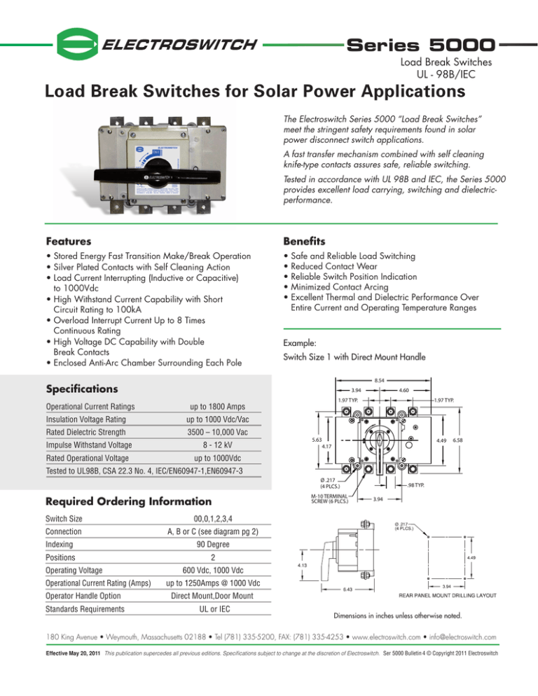
Series 5000 Load Break Switches UL - 98B/IEC Load Break Switches for Solar Power Applications The Electroswitch Series 5000 “Load Break Switches” meet the stringent safety requirements found in solar power disconnect switch applications. A fast transfer mechanism combined with self cleaning knife-type contacts assures safe, reliable switching. Tested in accordance with UL 98B and IEC, the Series 5000 provides excellent load carrying, switching and dielectricperformance. Features Benefits • Stored Energy Fast Transition Make/Break Operation • Silver Plated Contacts with Self Cleaning Action • L oad Current Interrupting (Inductive or Capacitive) to 1000Vdc •H igh Withstand Current Capability with Short Circuit Rating to 100kA •O verload Interrupt Current Up to 8 Times Continuous Rating •H igh Voltage DC Capability with Double Break Contacts •E nclosed Anti-Arc Chamber Surrounding Each Pole • • • • • Safe and Reliable Load Switching R educed Contact Wear R eliable Switch Position Indication M inimized Contact Arcing E xcellent Thermal and Dielectric Performance Over Entire Current and Operating Temperature Ranges Example: Switch Size 1 with Direct Mount Handle 8.54 Specifications Operational Current Ratings 3.94 up to 1800 Amps Insulation Voltage Rating up to 1000 Vdc/Vac Rated Dielectric Strength 3500 – 10,000 Vac Impulse Withstand Voltage 8 - 12 kV Rated Operational Voltage up to 1000Vdc 4.60 1.97 TYP. 5.63 1.97 TYP. 4.49 4.17 6.58 Tested to UL98B, CSA 22.3 No. 4, IEC/EN60947-1,EN60947-3 Ø .217 (4 PLCS.) Required Ordering Information Switch Size 00,0,1,2,3,4 Connection A, B or C (see diagram pg 2) Indexing Positions Operating Voltage Operational Current Rating (Amps) Operator Handle Option Standards Requirements M-10 TERMINAL SCREW (6 PLCS.) .98 TYP. 3.94 90 Degree 2 600 Vdc, 1000 Vdc up to 1250Amps @ 1000 Vdc Direct Mount,Door Mount UL or IEC Dimensions in inches unless otherwise noted. 180 King Avenue • Weymouth, Massachusetts 02188 • Tel (781) 335-5200, FAX: (781) 335-4253 • www.electroswitch.com • info@electroswitch.com Effective May 20, 2011 This publication supercedes all previous editions. Specifications subject to change at the discretion of Electroswitch. Ser 5000 Bulletin 4 © Copyright 2011 Electroswitch UL 98B UL98B RATINGS AT 1000 VDC CSA C22.2 NO.4-04 Switch Size: 1 2 4 Electrical Ratings: DC Rated Operational Current @ 1000VDC: le A 250 400 1250 40°C A 400 630 1800 Ui V 1000 1000 1000 Rated Impulse withstand voltage: Uimp kV 8 12 12 Short Circuit Making Capacity: Icm kA (Peak) 20kA 26kA 42kA DC Rated Thermal Current: lth Rated Insulation Voltage: Connection Capacity Rigid Cable (Cu) mm2 185 2 x 240 N/A Bar (Thickness / Width) mm2 5/25 2 x 5/40 2 x 7/80 Nm/ft-lb 18/13.3 24/17.7 55/40.6 10,000 10,000 10,000 kg/lb 1.9/4.2 4.2/9.3 20.8/45.9 Connection Diagram Bridging Links Terminal Shrouds Tightening Torque Mechanical Features Minimum Number of Operations without Load Max. Weight Accessories To meet UL requirements a switch must be completed with the terminal shrouds and bridging links depending on the connection diagram selected. (A, B or C) + – A + – B + + + – – + C IEC-EN-UNE 60947-1 IEC RATINGS AT 600 AND 1000 VDC IEC-EN-UNE 60947-3 Switch Size: 00 0 1 2 3 4 Electrical Ratings: DC Rated Operational Current: **DC21B 600VDC Ie A 20 65 315 700 1250 1800 1000VDC Ie A - - 250 500 850 1250 lth 40°C A 80 160 315 800 1250 1800 Ui V 800 1000 1000 1000 1000 1000 Rated Impulse withstand voltage: Uimp kV 8 8 8 12 12 12 Short Circuit Making Capacity: Icm kA (Peak) 5kA 13kA 20kA 26kA 60kA 42kA Rigid Cable (Cu) mm2 25 95 185 2 x 240 2 x 300 - Bar (Thickness / Width) mm2 - 5/25 7/25 2 x 5/40 2 x 10/50 2 x 7/80 Nm/ft-lb 2/1.5 13/9.6 18/13.3 24/17.7 45/33.2 55/40.6 30,000 30,000 20,000 10,000 10,000 10,000 kg/lb 0.4/0.9 1.0/2.2 1.9/4.2 4.5/9.9 7.6/16.8 20.8/45.9 DC Rated Thermal Current: Rated Insulation Voltage: Connection Capacity Tightening Torque Mechanical Features Minimum Number of Operations without Load Max. Weight ** Utilization Categories [Note: Suffix A/B refers to Frequent/Infrequent Operation] DC21: Resistive Load (including moderate overloads) DC22: Resistive and Inductive Loads DC23: Highly Inductive Loads 180 King Avenue • Weymouth, Massachusetts 02188 • Tel (781) 335-5200, FAX: (781) 335-4253 • www.electroswitch.com • info@electroswitch.com Effective May 20, 2011 This publication supercedes all previous editions. Specifications subject to change at the discretion of Electroswitch. Ser 5000 Bulletin 4 © Copyright 2011 Electroswitch
