Ku-Band Redundant
Block Downconverter Systems
BRKD1 Series
Features
• Standard 19” rack panel, 3.5” high
• Dual redundant power supplies
• Worldwide AC input capability
• Monitors converter bias currents and phase lock
to external reference
• Manual or automatic operation
• Manual override switch control knobs on rear
panel
• Serial I/O
• Offline I/O
• Frequency reference that is stable to ±20 ppb in
stand-alone operation
• 10.0 MHz external reference
Introduction
BRKD1 Series Ku-Band Redundant Block
Downconverter (BDC) systems contain either three
converters in a 1:2 redundant configuration or two
converters in a 1:1 redundant configuration. The
systems include automatic switchover logic, redundant
power supplies, and redundant ac line inputs. The
systems are designed for installation at satellite earth
stations in standard 19-inch EIA equipment racks. The
systems are designed to house BD-Series Ku-Band
Block Downconverters.
Options
• 10 dB gain
• 20 dB gain
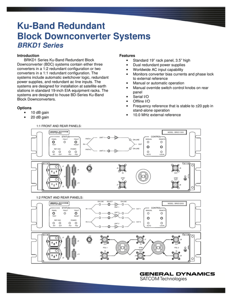
1:1 FRONT AND REAR PANELS:
MODEL: BRKD11XXX
STATUS
PANEL
FAULT
TEST
RESET
REF OSC
INT
PATH 1
FAULT
PS1
UNIT 1
ON-LINE
IN
POWER
EXT
CONTROL
MANUAL
REMOTE
AUTO
LOCAL
OUT
PATH 2
ON-LINE
UNIT 2
PS2
J12
J1
J5
J6
J4
REF
IN
OUT
STBY
IN
STBY
OUT
J3
J11
J7
J8
J2
1:2 FRONT AND REAR PANELS:
ON-LINE
SELECT
ON-LINE
MODEL: BRKD12XXX
UNIT 1
STATUS
IN 1
FAULT
PANEL
CONTROL
OUT 1
FAULT
MANUAL
REMOTE
AUTO
LOCAL
UNIT 3
TEST
RESET
REF OSC
POWER
IN 2
OUT 2
UNIT 2
INT
PS1
EXT
PS2
J12
J1
J8
J4
REF
J3
J11
J2
J5
J7
J9
OUT
IN
OUT
POL 1
STBY
POL 2
IN
OUT
IN
J10
J6
Operating Modes
• Automatic Mode
In Automatic mode, if a failure is detected in an online converter, the standby converter is switched on line.
Typical switchover time is 100 milliseconds. For 1:2
systems, in the case that both on-line converters fail,
priority is selectable to either Pol 1 or Pol 2. For either
1:1 or 1:2 systems, the unit will not automatically switch
to a defective converter.
• Manual Mode
The converters can also be manually switched from
the front panel or remotely. In Manual mode, automatic
switching will not occur upon fault detection, although
the monitor and alarm circuits still function.
1:1 System
Block Diagram
Local or Remote Control
The systems include provision for remote status
monitoring and operation. Typical uses are for sending
status information to a centralized monitor and control
system or for remotely controlling the system from a
nearby building. All Local front panel features can be
remotely controlled and monitored, except for the
Remote/Local switch. In Remote mode, the front panel
controls are inoperative, but the indicators continue to
reflect the current operating state of the system. Remote
status outputs are Form ‘C’ dry relay contacts capable of
switching up to 100 Vdc at 100 mA. Remote control
inputs are opto-isolator coupled for noise and common
mode ground loop rejection.
PD1
REFERENCE
MODULE 1
J12
EXT REF
IN
HY1
BDC
1
S1A
J5
POL 1
IN
S1B
J6
POL 1
OUT
REFERENCE
MODULE 2
BDC
2
HY2
J8
STBY
IN
J7
STBY
OUT
OFFLINE I/O
OFFLINE I/O
POWER/STATUS
POWER/STATUS
J3 - ALARMS
CONTROL
CONTROL
LOGIC
J4 - REM IN
STATUS
J11 - SER I/O
PS1
MOTOR
1
PS2
J1
LINE 1
110/220 Vac
POWER
SUPPLY 1
+15V, 5A
CURRENT
MONITOR 1
J2
LINE 2
110/220 Vac
POWER
SUPPLY 2
+15V, 5A
CURRENT
MONITOR 2
SENSOR 1
POWER TO BDC 1
SENSOR 2
POWER TO BDC 2
PD1
1:2 System
Block Diagram
REFERENCE
MODULE 1
J12
EXT REF
IN
HY 1
BDC
1
S1A
J5
POL 1
IN
S1B
J8
POL 1
OUT
REFERENCE
MODULE 3
BDC
3
HY 2
S2B
S2A
J6
POL 2
IN
J9
POL 2
OUT
REFERENCE
MODULE 2
BDC
2
HY 3
J7
STBY
IN
OFFLINE I/O
POWER/STATUS
POWER/STATUS
POWER/STATUS
J3 - ALARMS
J1
LINE 1
110/220 Vac
POWER
SUPPLY 1
+15V, 5A
J2
LINE 2
110/220 Vac
POWER
SUPPLY 2
+15V, 5A
PS2
MOTOR
2
CONTROL
CONTROL
LOGIC
J4 - REM IN
STATUS
J11 - SER I/O
PS1
J10
STBY
OUT
OFFLINE I/O
MOTOR
1
SENSOR 1
CURRENT
MONITOR 1
POWER TO BDC 1
SENSOR 2
CURRENT
MONITOR 2
POWER TO BDC 2
SENSOR 3
CURRENT
MONITOR 3
POWER TO BDC 3
†
Parameter
Notes
Min.
Configuration
BRKD11_ _ _ systems
BRKD12_ _ _ systems
BRKD1_F _ _ systems
BRKD1_B _ _ systems
BRKD1_J _ _ systems
BRKD1_C _ _ systems
BRKD1_F _ _ systems
BRKD1_B _ _ systems
BRKD1_J _ _ systems
BRKD1_C _ _ systems
BRKD1_ _ 10 systems
BRKD1_ _ 20 systems
Full band
Between BDCs
At +23 °C
At 1 dB compression (P1 dB)
Output, OIP3
@ 100 Hz offset
@ 1 kHz offset
@10 kHz offset
@100 kHz offset
@ 1 MHz offset
Linear
Parabolic
Ripple
Input (50 ohms)
Output (50 ohms)
RF input and output
External reference
Remote input
Alarm output
Serial I/O (RS-232/-422/-485)
1:1, One standby BDC for one main BDC
1:2, One standby BDC for two main BDCs
10.70
11.75
10.95
11.70
11.70
12.75
12.20
13.00
950
2000
950
1700
950
2000
950
1750
10
20
±1.0
±1.5
±1.0
16
20
+7
+10
+17
+20
-60
-70
-80
-90
-100
0.03
0.003
1.0
1.20
1.25
1.50
2.00
Type N Female (50 ohms)
Type BNC Female (50 ohms)
9-pin D Male
37-pin D Male
9-pin D Female
Manual or Automatic
Alarm is generated if phase lock is lost or
current draw is outside tolerance window
100 Vdc / 100 mA
Contact closure to ground;
withstand 5 V, sink 5 mA
0
+15
50
-105
-135
-145
-150
90–135 or 175–264
47
63
30
19 x 3.47 x 24
483 x 88.1 x 610
0
+50
Input Frequency Range
Output Frequency Range
System Gain
Gain Flatness
Gain Match
Noise Figure
Power Output
Third Order Intercept
Phase Noise
Group Delay
VSWR
Connectors
Operating Modes
Alarm Method
BDC phase lock/bias current
Alarm Output
Remote Inputs
Form ‘C’ contacts
Control inputs
External Reference
(10.0 MHz)
Level
Impedance
Phase Noise
Power Requirements
@ 10 Hz offset
@ 100 Hz offset
@ 1 kHz offset
@ 10 kHz offset
Voltage (autoranging)
Frequency
Power
Size
Temperature Range
Operating
Nom./Typ.
Max.
Units
GHz
GHz
GHz
GHz
MHz
MHz
MHz
MHz
dB
dB
dB
dB
dB
dBm
dBm
dBc/Hz
dBc/Hz
dBc/Hz
dBc/Hz
dBc/Hz
ns/MHz
2
ns/MHz
ns p-p
:1
:1
dBm
ohms
dBc/Hz
dBc/Hz
dBc/Hz
dBc/Hz
Vac
Hz
W
inches
mm
°C
* Specifications shown are for BD-Series BDCs. See product data sheet 16970 for spurious levels.
† When there is only one value on a line, the Nom./Typ. column is a nominal value; otherwise it is a typical value. Typical values are intended to
illustrate typical performance, but are not guaranteed.
Part Number/Ordering Information,
Ku-Band Redundant Block Downconverter Systems
BRKD1NNNN
System Type:
1:1 ........................................................................................ 1
1:2 ........................................................................................ 2
Frequency Band
(In / Out / LO)
10.70–11.75 GHz / 950–2000 MHz / 9.75 GHz .......................... F
10.95–11.70 GHz / 950–1700 MHz / 10.00 GHz......................... B
11.70–12.75 GHz / 950–2000 MHz / 10.75 GHz......................... J
12.20–13.00 GHz / 950–1750 MHz / 11.25 GHz.........................C
Gain
10 dB min. ......................................................................................... 1 0
20 dB min. ......................................................................................... 2 0
Examples:
Order Number
• 1:1 system with 10.95–11.70 GHz input, 950–1700 MHz output, 20 dB gain
BRKD11B20
• 1:2 system with 12.20–13.00 GHz input, 950–1750 MHz output, 10 dB gain
BRKD12C10
Other Products
•
•
•
•
•
•
•
•
•
Solid-State Power Amplifiers and SSPA Systems
Solid-State Power BUCs and SSPB Systems
Low Noise Amplifiers and LNA Systems
Low Noise Block Converters and LNB Systems
Block Up and Block Down Converters
Synthesized Converters
Line Drive Amplifiers
Power Supply Monitors
Redundant Control Panels for SSPAs, SSPBs, and LNAs
60 Decibel Road, Suite 200 • State College, PA 16801 USA • Tel. +1-814-238-2700 • FAX +1-814-238-6589
Email: satcom@gd-ms.com • www.gdsatcom.com/electronics.php
© 2015 General Dynamics. All rights reserved. General Dynamics reserves the right to make changes to its products and specifications at any time and without notice.
All trademarks indicated as such herein are trademarks of General Dynamics. All other product and service names are the property of their respective owners.
19380
Rev. A


