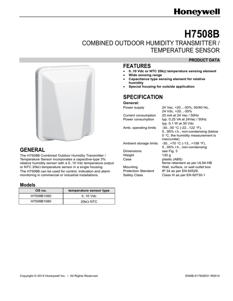
H7508B
COMBINED OUTDOOR HUMIDITY TRANSMITTER /
TEMPERATURE SENSOR
PRODUCT DATA
FEATURES
0..10 Vdc or NTC 20k temperature sensing element
Wide sensing range
Capacitance type sensing element for relative
humidity
Special housing for outside application
SPECIFICATION
General:
Power supply
Current consumption
Power consumption
Amb. operating limits
Ambient storage limits
GENERAL
The H7508B Combined Outdoor Humidity Transmitter /
Temperature Sensor incorporates a capacitive-type 3%
relative humidity sensor with a 0..10 Vdc temperature output
or NTC 20k temperature sensor in a single housing.
The H7508B can be used for control, indication and alarm
monitoring in commercial or industrial installations.
Dimensions
Weight
Case
Mounting
Protection Standard
Safety Class
24 Vac, +20...-30%; 50/60 Hz,
24 Vdc, +20...-30%
20 mA at 24 Vac / 50Hz
typ. 0.25 VA at 24Vac / 50Hz
typ. 0.1 W at 30 Vdc
-30...50 C (-22...122 F),
5...95% r.h., non-condensing (below
0 C, the humidity measurement is
inaccurate)
-30...+70 C (-13...+158 F),
5...95% r.h., non-condensing
see Fig. 3
130 g
plastic (ABS)
flame retardant as per UL94-HB
Wall, surface, or wall outlet box
IP 34 as per EN 60529,
Class III as per EN 60730-1
Models
OS no.
temperature sensor type
H7508B1060
0..10 Vdc
H7508B1080
20k NTC
Copyright © 2014 Honeywell Inc. • All Rights Reserved
EN0B-0179GE51 R0514
H7508B COMBINED OUTDOOR HUMIDITY TRANSMITTER / TEMPERATURE SENSOR – PRODUCT DATA
Relative Humidity
Temperature
Temp. sensing range:
-30...50 C (-22...158 F)
Nominal value
NTC 20k
20 k at 25 C
Output signal
0..10Vdc
Accuracy
0..10 Vdc
NTC 20k
Hum. sensing range
Output signal
Accuracy class
Temp. compensation
0..10 V proportional to -30 .. 50 °C
resolution ≤ 0.05 K
max. 2 mA sink/source current
short-circuit protected
Accuracy (at 25 °C ambient)
5...10% r.h.
10%
10...30% r.h.
5%
30...70% r.h.
3%
70...90% r.h.
5%
90...95% r.h.
10%
max. 1.2 K in range 5 .. 50 °C
0.3 K at 25 C
Response time
0..10Vdc
NTC 20k
EN0B-0179GE51 R0514
5...95% r.h.
0...10 V proportional to 0...100% r.h.
resolution ≤ 0.05% r.h.
max. 2 mA sink/source current
short-circuit protected
3%
in range 5 .. 50 °C
Response time
1/e < 1 min
0.5 < 11 min
Response time
2
0.9 < 20 s
H7508B COMBINED OUTDOOR HUMIDITY TRANSMITTER / TEMPERATURE SENSOR – PRODUCT DATA
INSTALLATION
Wiring
SENSOR
!
230 VAC
1
24 VAC
2
CONTROLLER
6
5
7
TRANSFORMER FOR
SENSORS/TRANSMITTERS
AND ACTUATORS
0...10 V
!
rh INPUT
0...10 V
TEMP. INPUT
230 VAC
24 VAC
COMMON
COMMON
TRANSFORMER FOR
CONTROLLER
Fig. 1. Wiring example, H7508B1060
SENSOR
!
230 VAC
1
24 VAC
2
CONTROLLER
6
3
4
7
0...10 V
!
rh INPUT
NTC 20 kΩ
NTC INPUT A
NTC INPUT B
NTC 20 kΩ
COMMON
24 VAC
230 VAC
COMMON
TRANSFORMER FOR
CONTROLLER
TRANSFORMER FOR
SENSORS/TRANSMITTERS
AND ACTUATORS
Fig. 2. Wiring example, H7508B1080
Terminal #
1
2
3
4
5
6
7
8
9
10
Table 1. Terminal assignment
H7508B1060
H7508B1080
24 V ~ (AC or positive DC power supply)
24 V ~ (AC or positive DC power supply)
24 V ┴ (AC common or negative DC power supply)
24 V ┴ (AC common or negative DC power supply)
Not connected
NTC 20 kΩ
Temperature output 0..10 V
Humidity output 0..10 V
COM = 24 V ┴
Not connected
Humidity output 0..10V
COM = 24 V ┴
Not connected
Not connected
NOTE: Use two separate safety transformers, one for sensors/transmitters and actuators and one for the controller (see Fig.
1).
Accepted wires are solid/stranded 0.34 … 1.3 mm2 (AWG 22 …16), max. terminal screw tightening torque: 0.5 Nm
(4.4 lb-in).
Max. wire length is 200 m (660 ft) between the transmitter and the controller.
Keep 15 cm (5.9’’) min. distance between sensor lines and 230 Vac power lines.
Installation of the product near high EMI-emitting devices may lead to faulty measurements. Use shielded wiring in
areas with high EMI.
Mounting Advice
Mount the product where it is protected against rain and direct sun radiation, preferably on the north side of the building. If
this is not practical, it should be shielded from the sun’s rays.
Mount the product preferably on that outside wall of the buildings having windows of the main occupancy rooms to be
controlled.
Provide sufficient air circulation for accurate measurement.
To avoid false measurement due to warm air drafts from the conduit, seal the cable conduit.
To prevent rain water from entering the sensor housing, ensure that the cable inlet holes on the product housing are sealed
properly and that the cable runs from the bottom to the top into the cable entry.
Do not mount the product over windows, doors, air extractors, or other heat sources or underneath the eaves of the roofs or
a balcony.
3
EN0B-0179GE51 R0514
H7508B COMBINED OUTDOOR HUMIDITY TRANSMITTER / TEMPERATURE SENSOR – PRODUCT DATA
DIMENSIONS
60 (2.36)
20 (0.79)
172 (6.77)
132 (5.2)
95 (3.74)
11 (0.43), 2X
4.2 (0.17), 4X
Honeywell
118.5 (4.67)
85 (3.35)
100.5 (3.96)
4.6 (0.18), 2X
23.5 (0.93)
Fig. 3. Dimensions of special housing in mm (inches)
Manufactured for and on behalf of the Environmental and Combustion Controls Division of Honeywell Technologies Sàrl, Rolle, Z.A. La Pièce 16, Switzerland by its Authorized Representative:
Automation and Control Solutions
Honeywell GmbH
Böblinger Strasse 17
71101 Schönaich, Germany
Phone +49 (0) 7031 637 01
Fax
+49 (0) 7031 637 740
http://ecc.emea.honeywell.com
EN0B-0179GE51 R0514
Subject to change without notice


