Enpirion® Power Evaluation Board
EN5365QI 6A Buck PowerSoC
With VID Output Voltage Select
Evaluation Board User Guide
Description
This is the EN5365QI User Guide. The
EN5365QI features an integrated inductor,
power MOSFETS, controller, a bulk of the
compensation network, and protection circuitry
against system faults. The EN5365QI features
a 3 pin VID output voltage selector. The 3 pin
VID allows the user to choose from one of
seven predefined output voltage settings. This
level of integration delivers a substantial
reduction in footprint and parts count over
competing solutions. The evaluation board is
optimized for engineering ease of testing
through programming options, clip leads, test
points etc.
Evaluation Board Over View
1
2
6
3
5
7
8
4
4
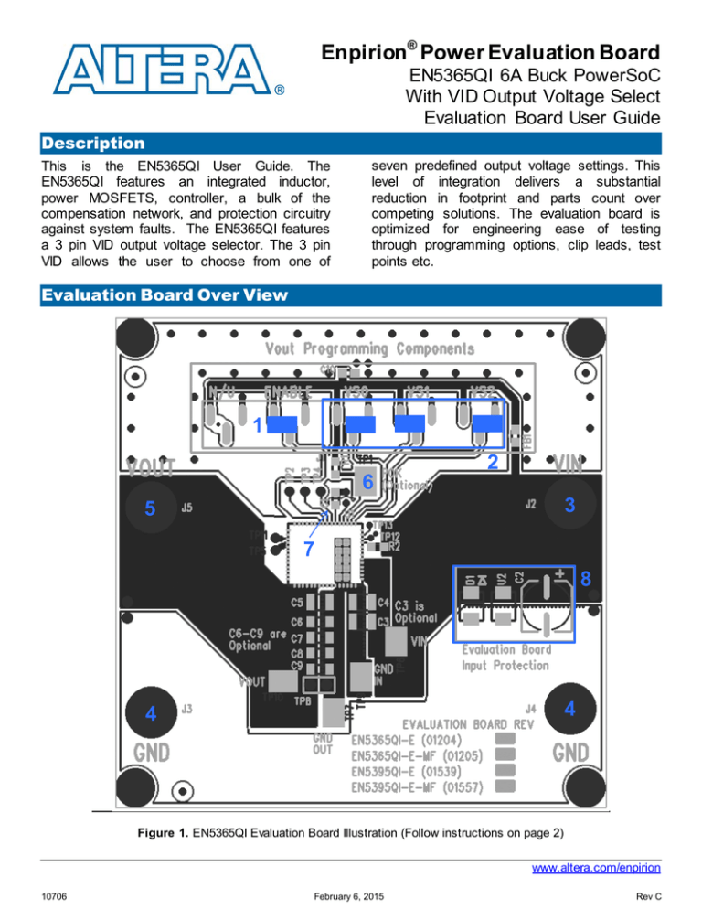
Figure 1. EN5365QI Evaluation Board Illustration (Follow instructions on page 2)
www.altera.com/enpirion
10706
February 6, 2015
Rev C
EN5365QI Evaluation Board
Instructions
The numbers in the instructions below correspond
to the numbers in Figure 1. By following the number
sequence below, the device can be turned on by
step 5.
1) ENABLE – The jumper on the left two pins
enables the device by connecting ENABLE
to AVIN. Remove this jumper and then
connect it to the right two pins to connect
ENABLE to ground and disable the device.
Leave the pins open and use an external
signal to the center pin to toggle the
ENABLE on (>1.8V) and off (<0.8V).
2) Output Voltage Settings (VSx) - As
shown, output voltage is set to 1.8V. The
left pin of VS2, VS1, VS0 pulls VS2, VS1,
VS0 pin to AVIN (high = 1), respectively.
The right pin pulls the VS2, VS1, VS0 pin to
ground (low = 0). DO NOT change the
output voltage when the device is in
regulation; otherwise, damage may occur.
Follow the Table below for other output
voltage settings.
VS2
VS1
VS0
VOUT
0
0
0
0
1
1
1
1
0
0
1
1
0
0
1
1
0
1
0
1
0
1
0
1
3.3V
2.5V
1.8V
1.5V
1.25V
1.2V
0.8V
Reserved
3) PVIN (J2) - Connect 2.5V to 5.5V supply on
J2 (VIN). Do not turn on until everything is
connected correctly.
4) Ground (J3 and J4) - Connect the input
supply ground to J4 and the output ground
to J3.
5) VOUT (J5) - Connect the load to J5. If the
instructions were followed up to this point,
the device may be powered to turn on.
6) POK - This is the open drain POK flag,
which is pulled up to AVIN by R1. When
VOUT is between 90% and 120% of the
nominal regulation output voltage, POK will
be pulled high to AVIN; otherwise, the POK
pin is pulled low.
7) Soft Start Capacitor (C1) – The soft start
capacitor is by defaulted 15nF and can be
adjusted to increase or decrease the softstart time. See the equation below.
Tss [s] = Css [F] * 75
The soft-start time (Tss) is in seconds and
the soft-start capacitance (Css) is in Farads.
See Datasheet for details.
8) Input Protection – The EN5365QI
evaluation board comes with some input
polarity protection.
www.altera.com/enpirion, Page 2
10706
February 6, 2015
Rev C
EN5365QI Evaluation Board
Evaluation Board Schematic
www.altera.com/enpirion, Page 3
10706
February 6, 2015
Rev C
EN5365QI Evaluation Board
Bill of Materials
Designator
C1
C2
U2
D1
R1
R2
C10
FB1
C4,C9
C3,C5, C6,C7,C8
U1
Qty
Description
1
1
1
1
1
1
1
1
2
5
1
15000PF 10% 50V SMD 0805 X7R CERAMIC CHIP CAPACITOR
CAPACITOR, SMT ELECTROLYTIC, 150UF, 20%, 10V
TRANSIENT VOLTAGE SUPPRESSOR, 6.5V, BIDIRECTIONAL, SMT
S2A DIODE
RES 5.62K OHM 1/8W 1% 0805 SMD
COMPONENT NOT USED ** DO NOT INSTALL **
CAP, 10UF, 0805, 10%, X5R
MULTILAYER SMD FERRITE BEAD 4000MA 0805
CAP, 47UF, 10V, X5R, 1210
COMPONENT NOT USED ** DO NOT INSTALL **
EN5365QI QFN 6A PowerSoC with VID Output Voltage Select
www.altera.com/enpirion, Page 4
10706
February 6, 2015
Rev C
EN5365QI Evaluation Board
Test Recommendations
To guarantee measurement accuracy, the following precautions should be observed:
1. Make all input and output voltage measurements at the board using the test points provided
as this will eliminate voltage drop across the line and load cables that can produce false
readings.
2. Measure input and output current with series ammeters or accurate shunt resistors. This is
especially important when measuring efficiency.
3. Use a low-loop-inductance scope probe tip similar to the one shown below to measure
switching signals and input / output ripple to avoid noise coupling into the probe ground
lead. Input ripple, output ripple, and load transient deviation are best measured near the
respective input / output capacitors. For more accurate ripple measurement, please see
Altera Enpirion App Note regarding this subject.
4. The board includes a pull-up resistor for the POK signal and ready to monitor the power OK
status at clip lead marked POK.
Contact Information
Altera Corporation
101 Innovation Drive
San Jose, CA 95134
Phone: 408-544-7000
www.altera.com
© 2015 Altera Corporation—Confidential. All rights reserved. ALTERA, ARRIA, CYCLONE, ENPIRION, HARDCOPY, MAX, MEGACORE, NIOS, QUARTUS and STRATIX
words and logos are trademarks of Altera Corporation and registered in the U.S. Patent and Trademark Office and in other countries. All other words and logos identif ied as
trademarks or service marks are the property of their respective holders as described at www.altera.com/common/legal.html. Altera warrants performance of its semiconductor
products to current specifications in accordance with Altera's standard warranty, but reserves the right to make changes to any products and serv ices at any time without
notice. Altera assumes no responsibility or liability arising out of the application or use of any information, product, or service described herein except as expressly agreed to in
writing by Altera. Altera customers are advised to obtain the latest version of device specifications before relying on any published information and bef ore placing orders f or
products or serv ices.
www.altera.com/enpirion, Page 5
10706
February 6, 2015
Rev C


