1
Minimum Hardware Requirements
Intel® Compute
Module MFS2600KI
Quick Start User's Guide
To avoid integration difficulties and possible
damage to your system, make sure you
have components from each category below.
2
Preparing
the Module
Observe normal ESD
(Electrostatic Discharge)
procedures.
Remove Top Cover
Depress cover release button.
B
Slide top cover toward rear and lift upward.
■ Processor(s):
• Minimum of one Intel® Xeon® processor
E5-2600 series.
Thank you for buying an Intel® Compute Module.
The following information will help you
assemble your Intel® Compute Module MFS2600KI
and install components.
■ Memory:
• Minimum of one 1024-MB,
DDR3 1066/1333/1600-MT/s RDIMM,
UDIMM or LR-DIMM.
Check your
Intel® Compute
Module to ensure no
components have
loosened during
shipping.
B
C
Always touch the module
chassis first, before reaching
inside to make connections or
to install components.
LO
S
E
1s
t
O
P
EN
1s
t
C
LO
S
E
1s
t
O
P
EN
1s
This guide and other supporting documents
are located on the web at
http://support.intel.com/support/motherboards/server/MFS2600KI/.
Before proceeding
further, do the
following:
A
Place your
Intel® Compute Module
on a flat anti-static surface
to perform the following
integration procedures.
■ Heatsink(s):
• Minimum of one 1U Intel approved
passive heatsink.
IMPORTANT!
A
t
If you are not familiar with ESD (Electrostatic Discharge) procedures
used during system integration, please see the Intel® Compute Module
MFS2600KI User Guide, available at
http://support.intel.com/support/motherboards/server/MFS2600KI/.
3
4
Remove the Air Duct
Remove Heatsink(s)
Read all cautions and warnings before starting your compute module integration.
CAUTION: The heatsink has thermal interface material (TIM) on the
underside of it. Use caution so that you do not damage the thermal
interface material. Use gloves to avoid sharp edges.
C
A
3
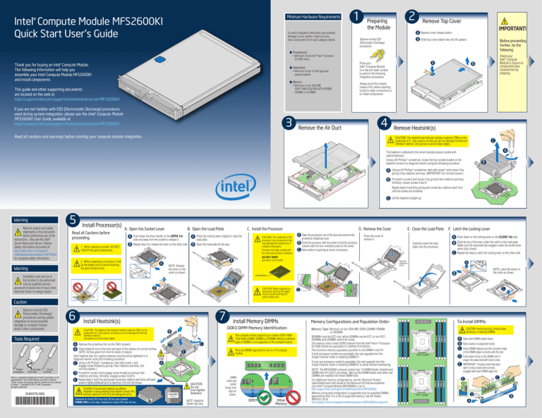
The heatsink is attached to the server board/processor socket with
captive fasteners.
Using a #2 Phillips* screwdriver, loosen the four screws located on the
heatsink corners in a diagonal manner using the following procedure:
2
Using a #2 Phillips* screwdriver, start with screw 1 and loosen it by
giving it two rotations and stop. (IMPORTANT: Do not fully loosen.)
B
Proceed to screw 2 and loosen it by giving it two rotations and stop.
Similarly, loosen screws 3 and 4.
C
A
B
1
LO
S
E
1s
t
O
4
P
EN
1s
t
C
LO
S
E
1s
t
P
EN
1s
t
C
Warning
5
Install Processor(s)
Read all Cautions before
proceeding.
1. When opening a socket, DO NOT
TOUCH the gold socket wires.
A. Open the Socket Lever
A
B
B. Open the Load Plate
Push down the lever handle on the OPEN 1st
side and away from the socket to release it.
A
Repeat step A to release the lever on the other side.
B
C. Install the Processor
Press the locking lever slightly to raise the
load plate.
CAUTION: The underside of the
processor has components that
may damage the socket pins if
installed improperly.
Processor must align correctly with
the socket opening before installation.
DO NOT DROP
processor into socket!
Open the load plate all the way.
N
ON
XC
FO
ON
XC
FO
N
A2
LG
A20
LG
ILM
17
56
2
2
56
A
D. Remove the Cover
A
B
C
Take the processor out of the box and remove the
protective shipping cover.
Orient the processor with the socket so that the processor
cutouts match the four orientation posts on the socket.
Note location of gold key at corner of processor.
E. Close the Load Plate
Press the cover to
remove it.
F. Latch the Locking Lever
A
B
Carefully lower the load
plate over the processor.
C
Push down on the locking lever on the CLOSE 1st side.
Slide the tip of the lever under the notch in the load plate.
Make sure the load plate tab engages under the socket lever
when fully closed.
Repeat the steps to latch the locking lever on the other side.
A
Save the
protective
cover.
B
1
01
A2
LG
ILM
Components
NOTE: Latch the levers in
the order as shown.
N
ON
XC
NOTE: Release
the levers in the
order as shown.
Lift the heatsink straight up.
FO
17
Installation and service of
this product to be performed
only by qualified service
personnel to avoid risk of injury from
electrical shock or energy hazard.
A
17
Warning
ILM
1
2. When unpacking a processor, hold
by the edges only to avoid touching
the gold contact wires.
11
1
01
Read all caution and safety
statements in this document
before performing any of the
instructions. Also see the Intel®
Server Board and Server Chassis
Safety Information document at:
http://www.intel.com/support/
motherboards/server/sb/cs-010770.htm
for complete safety information.
Pr
o
So ces
ck so
et r
O
Repeat steps A and B by giving each screw two rotations each time
until all screws are loosened.
2
56
2
B
B
B
CAUTION: When unpacking a
processor, hold by the edges
only to avoid touching the
gold contact pins.
C
C
Caution
D
1
Only use DIMMs approved for use in a 1U compute
module.
4
DIMM G1
DIMM G2
DIMM H1
DIMM H2
DIMM F2
DIMM F1
DIMM E2
CPU 2 Socket
D
Other
Memory
DIMM A1
DIMM A2
t
DDR3
DIMM B1
1s
NOTE: Heatsink
styles may vary.
DIMM B2
E
(26 Fins)
DIMM D2
S
CAUTION:
Do not
over-tighten
fasteners.
DIMM
notch and
socket
bump must
align as
shown.
NOTE: The MFS2600KI compute module has 14 DIMM blanks installed and
DIMM slots A1 and E1 are empty. Take out the DIMM blanks only when real
DIMMs are installed into those DIMM slots.
For additional memory configurations, see the Technical Product
Specification and User Guide on the Resource CD that accompanied
your Intel® Compute Module MFS2600KI or go to:
http://support.intel.com/support/motherboards/server/MFS2600KI/.
Memory sizing and configuration is supported only for qualified DIMMs
approved by Intel. For a list of supported memory, see the Tested
Memory List at
http://support.intel.com/support/motherboards/server/MFS2600KI/compat.htm.
A
B
C
E
DIMM D1
LO
t
Front CPU
CAUTION: Avoid touching contacts when
handling or installing DIMMs.
DIMM C2
C
1s
Heatsink for front CPU has only 26 fins and marked
FRONT CPU on the side. Heatsink for back CPU has 42 fins.
LGAFRO
201 N
1-G T C
590 P
08-0 U
01-F
XC
Memory Type: Minimum of one 1024-MB, DDR3 UDIMM, RDIMM
or LRDIMM.
RDIMMs must be ECC only, while UDIMMs can be ECC or non-ECC.
RDIMMs and UDIMMs cannot be mixed.
The memory slots of each DDR3 channel from the Intel® Xeon® Processor
E5-2600 Series are populated in a farthest-first fashion.
The minimum memory population possible is one DIMM in slot A1.
If both processor sockets are populated, the next upgrade from the
Single Channel mode is installing DIMM E1.
If only one processor socket is populated, the next upgrade from the
Single Channel mode is installing DIMM B1 to allow channel interleaving.
EN
CAUTION: Front and back heatsinks are different.
Installation of wrong heatsink (front heatsink to back CPU
and back heatsink to front CPU) will damage the server.
This compute module supports up to sixteen DDR3-1066/
1333/1600 UDIMM, RDIMM or LRDIMM. Mixing of different
types of DIMMs is not supported on this compute module.
To Install DIMMs:
Memory Configurations and Population Order:
DIMM E1
C
E
t
on
Fr
G46370-002
3
le
du
Mo
Intel is a registered trademark of Intel Corporation or its
subsidiaries in the United States and other countries.
*Other names and brands may be claimed as the property
of others. Copyright © 2012, Intel Corporation.
All rights reserved.
FL
AIR
Remove the protective film on the TIM if present.
2
Align heatsink fins to the front and back of the chassis for correct airflow.
NOTE: Airflow goes from front-to-back of chassis.
Each heatsink has four captive fasteners and should be tightened in a
TIM
diagonal manner using the following procedure:
A
C Using a #2 Phillips* screwdriver, start with screw 1 and
engage screw threads by giving it two rotations and stop. (Do
not fully tighten.)
D Proceed to screw 2 and engage screw threads by giving it two
rotations and stop. Similarly, engage screws 3 and 4.
E Repeat steps C and D by giving each screw two rotations each time until each
screw is lightly tightened up to a maximum of 8 inch-lbs torque.
OW
P
1/4-inch
nut driver
DDR3 DIMM Memory Identification:
B
A
B
Install Memory DIMMs
O
Anti-static
wrist strap
CAUTION: The heatsink has thermal interface material (TIM) on the
underside of it. Use caution so that you do not damage the thermal
interface material.
Use gloves to avoid sharp edges.
ute
mp
Co
Phillips*
screwdriver
7
Install Heatsink(s)
DIMM C1
Tools Required
6
Pr
o
So ces
ck so
et r
Observe normal ESD
[Electrostatic Discharge]
procedures during system
integration to avoid possible
damage to compute module
and/or other components.
Open both DIMM socket levers.
Note location of alignment notch.
Insert DIMM making sure the connector edge
of the DIMM aligns correctly with the slot.
Push down firmly on the DIMM until it
snaps into place and both levers close.
IMPORTANT! Visually check that each
latch is fully closed and correctly
engaged with each DIMM edge slot.
C
E
D
CPU 1 Socket
A
B
9
Install TPM Module
To install the TPM module, insert the
standoff into the hole in the board and
insert the TPM module connector into
the connector in the board. Press down
gently but firmly to ensure that the
module is properly seated in the
connectors, and then tighten the tamper
resistant screw.
Front Panel Connectors and Indicators
Install Processor Air Duct
Install processor air
duct as shown.
J
I
Standoff
A
B
C
D E
F
H
E. NIC1 and NIC2 Activity LEDs
F. Disk Activity LED
G. ID LED
H. Power Button
I. Fault LED
J. Power LED
C
G
LO
S
E
1s
t
A.
B.
C.
D.
O
P
EN
1s
t
LO
S
E
1s
t
EN
1s
t
Component Layout
Install Mezzanine Card
Risk of explosion if battery is replaced
with an incorrect type. Batteries should
be recycled where possible. Disposal of
used batteries must be in accordance
with local environmental regulations.
LO
C
S
LO
E
S
t
1s
1s
E
t
O
P
P
EN
O
t
1s
1s
EN
DIMM G1
C
Mezzanine
Card
Connector
120
DIMM G2
Mezzanine
Card
Connector
40
DIMM H1
C
DIMM H2
With a Phillips* screwdriver, remove
the four screws on the server board.
CAUTION
DIMM F2
B
With a 1/4-inch nut driver, install the four
standoffs that shipped with the mezzanine
card in the same holes that were just
vacated by the screws.
Midplane
Guide Pin
Receptacle
DIMM F1
C
Midplane
Signal
Connector
Midplane
Power
Connector
DIMM E2
Hold mezzanine card by its edges and
remove from packaging. Remove
the protective connector cover from
the mezzanine card.
DIMM E1
B
P
A
O
10
C
le
odu tor
M
ec
TPMConn
USB Ports 0 and 1
USB Ports 2 and 3
Video Port
NIC3 and NIC4 Activity LEDs
Activity LEDs
t
C
LO
C
S
LO
E
S
t
1s
1s
E
t
O
P
P
EN
O
t
1s
1s
EN
t
CMOS
Clear
2
J1F8
D
d
Car
ine
an
ezz
3
Password
Clear
2
J1F7
3
M
SATA
Enabled
Default
Clear
CPU 1 Socket
TPM
Default
Password
Clear
eUSB
SSD
CMOS Battery
C
E
E
S
S
LO
LO
C
1s
t
t
1s
O
EN
EN
P
P
O
1s
t
t
1s
USB
0-1
See your Intel ® Compute Module MFS2600KI User Guide
for expanded component and connection information.
USB
2-3
Video
C
E
E
S
S
LO
LO
C
NIC3 NIC1 HDD
LED LED LED
NIC4 NIC2 ID
LED LED LED
1s
t
t
1s
O
EN
EN
P
P
O
1s
t
t
1s
Diagnostic LED Information
11
A
B
DIMM A1
3
Default
DIMM A2
J1F5
Recover
DIMM B1
2
Default
DIMM B2
E
ard
ME
Force
Update
Enabled
DIMM D2
3
BIOS
Recovery 2
J1F4
3
Secure mezzanine card to standoffs with the
four screws previously removed.
eC
in
zan
z
Me
E
J1F3
Default
DIMM D1
Position the mezzanine card above the mezzanine card connectors on the server board and align the
four holes with the standoffs. Carefully press the mezzanine card into place until it is fully seated in
the connectors and resting on the standoff supports.
2
DIMM C2
D
CPU 2 Socket
BMC
Force
Update
DIMM C1
Side 2
8
LED Name
Install Top Cover
Function
Color
Power LED
Identifies power
state of compute module
Green
Fault LED
Identifies fault warning
Amber
ID LED
Provides an aid in
identifying a compute
module from the front panel
Blue
Use Intel® Modular Server Control
UI to turn ID LED on or off
Drive Activity LED
Indicates drive
activity
Green
Off = No drive activity
Blink = Drive activity
NIC1 - NIC2 LEDs
Indicates network
activity and link
Green
Blink = Outbound Activity
NIC3 - NIC4 LEDs
Indicates network
activity and link of
NICs on I/O mezzanine
card
Green
Off = No link
On = Link established
Blink = Activity
A
Align top cover over corresponding notches in module chassis.
Slide top cover forward to close.
B
Indicator
Off = Power is off
On = Power on
Slow Blink = Power is in standby or
sleeping mode
Off = No Ready/OK
Solid On = Critical or
non-recoverable error
1Hz Blink = Non-critical or
recoverable error
Power Power/
Button Fault
LEDs
C
LO
S
E
1s
t
O
P
EN
1s
t
C
LO
S
E
1s
t
O
P
EN
1s
t


