Catalog Number:
Date:
Project:
OVERVIEW
The nLight nPP16 family of power packs is the workhorse of an nLight system, delivering robust system
performance and design versatility for commercial and industrial lighting control applications. The nPP16
family is capable of switching loads up to 16 Amps via an internal latching relay designed with robust
protection from the harsh switching requirements of T5 fluorescent and LED loads. These power packs also
provide nLight system bus power - up to 40mA from each of its two RJ-45 ports - by transforming Class 1
line voltage (120/277 VAC or 347 VAC) to Class 2 low voltage (15 VDC). This power is typically utilized by
other nLight devices within the power pack’s local control zone; however, remaining power is also made
available over the network for Bridges and devices in other zones to utilize.
FEATURES
•
•
•
•
•
•
•
Communicates w/ nLight Network
Self-Contained Relay Switches Line Voltage Load
Supplies 40mA of Bus Power / RJ-45 port
Remotely Configurable/Upgradeable
Push-Button Programmable
Configurable Relay Logic
Extended Chase Nipple
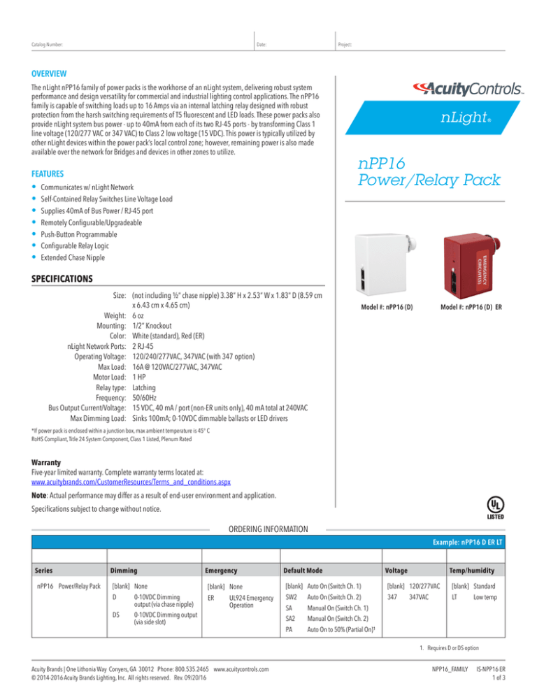
nPP16
Power/Relay Pack
SPECIFICATIONS
Size: (not including ½” chase nipple) 3.38” H x 2.53” W x 1.83” D (8.59 cm
x 6.43 cm x 4.65 cm)
Weight: 6 oz
Mounting: 1/2” Knockout
Color: White (standard), Red (ER)
nLight Network Ports: 2 RJ-45
Operating Voltage: 120/240/277VAC, 347VAC (with 347 option)
Max Load: 16A @ 120VAC/277VAC, 347VAC
Motor Load: 1 HP
Relay type: Latching
Frequency:50/60Hz
Bus Output Current/Voltage: 15 VDC, 40 mA / port (non-ER units only), 40 mA total at 240VAC
Max Dimming Load: Sinks 100mA; 0-10VDC dimmable ballasts or LED drivers
Model #: nPP16 (D)
Model #: nPP16 (D) ER
*If power pack is enclosed within a junction box, max ambient temperature is 45° C
RoHS Compliant, Title 24 System Component, Class 1 Listed, Plenum Rated
Warranty
Five-year limited warranty. Complete warranty terms located at:
www.acuitybrands.com/CustomerResources/Terms_and_conditions.aspx
Note: Actual performance may differ as a result of end-user environment and application.
Specifications subject to change without notice.
ORDERING INFORMATION
Example: nPP16 D ER LT
Series
nPP16 Power/Relay Pack
Dimming
[blank] None
D
DS
0-10VDC Dimming
output (via chase nipple)
0-10VDC Dimming output
(via side slot)
Emergency
[blank] None
ER
UL924 Emergency
Operation
Default Mode
[blank] Auto On (Switch Ch. 1)
SW2
Auto On (Switch Ch. 2)
SA2
Manual On (Switch Ch. 2)
SA
PA
Manual On (Switch Ch. 1)
Voltage
Temp/humidity
[blank] 120/277VAC
347
347VAC
[blank] Standard
LT
Low temp
Auto On to 50% (Partial On)¹
1. Requires D or DS option
Acuity Brands | One Lithonia Way Conyers, GA 30012 Phone: 800.535.2465 www.acuitycontrols.com
© 2014-2016 Acuity Brands Lighting, Inc. All rights reserved. Rev. 09/20/16
NPP16_FAMILY IS-NPP16 ER
1 of 3
WIRING (Do not wire hot)
T568B pin/pair assignment is recommended for all CAT-5e cables. For Supply Connections, use 14 AWG/90°C, 12 AWG/75°C or larger.
Diagram for non-dimming units
Diagram for units with a dimming option (-D or -DS suffix)
BLU (line in)
WHT (neutral)
BLK1 (line in)
nPP16
120 VAC
OR
277 VAC1
ORN1 (line in)
BLU (line in)
BLU (line out)
120 VAC BLK1 (line in)
OR
1
277 VAC1 ORN (line in)
nPP16 D
or
nPP16 DS
WHT(neutral)
LOAD
CAT-5e
BLU (line out)
CAT-5e
0-10 VDC
Ballast or
LED Driver
VIO (low voltage dim out)
GRY (low voltage common)
GRN
Note 1
BLK - 120 VAC
ORN - 277 VAC (or 347 VAC if unit has 347 option)
WIRING FOR EMERGENCY (-ER) UNITS
T568B pin/pair assignment is recommended for all CAT-5e cables. Unit powers itself but does not provide any bus power to other connected nLight devices.
For Supply Connections, use 14 AWG/90°C, 12 AWG/75°C or larger.
Diagram for non-dimming units
Diagram for units with a dimming option (-D or -DS suffix)
Emergency
3
VIO
{
{
{
Normal
(sense only)
(low voltage
dim out)
GRY (low voltage
OPTIONAL
TEST
SWITCH
BLK
(Normal Feed)
WHT
YEL
nPP16 ER
RED
OPTIONAL
TEST
120 VAC
OR
277 VAC1
BLU (Switched Out)
WHT w/ RED
STRIPE
nPP16 D ER
or
nPP16 DS ER
SWITCH
BLK
BLU (Emer. Feed)
(Normal Neutral)
CAT-5e
common)
(120VAC
Emer. Feed)
(277VAC
Emer. Feed2)
(Normal Feed)
EMERGENCY
LOAD
Emergency
EMERGENCY
0-10 VDC
Ballast or
LED Driver
YEL
RED
{
Normal3
(sense only)
(120VAC
Emer. Feed)
(277VAC
Emer. Feed2)
120 VAC
OR
277 VAC1
BLU (Emer. Feed)
BLU (Switched Out)
WHT
(Normal Neutral)
WHT w/ RED
STRIPE
(Emer. Neutral)
CAT-5e
Notes
(Emer. Neutral)
GRN
1. Connect to 120VAC or 277VAC feed ONLY. Cap off unused wire.
2. For 347V product, Red wire is 347VAC Emer. Feed
3. Normal Sense input: 120-277VAC. For 347V product: 120-347VAC
GENERAL INSTALLATION INSTRUCTIONS
• Mount through a ½” knockout in any junction box or luminaire. Secure with lock nut.
• Following above wiring diagram, connect wires to line voltage feed(s), neutral(s), and load.
• If applicable, connect low voltage violet and gray dimming wires to 0-10 VDC ballast/driver and
•
green wire to an approved ground connection. Note: wires have 600V rated insulation.
Interconnect unit (via RJ-45 ports) with other nLight devices in lighting zone using CAT-5e cables.
BUTTON
RJ-45 PORTS
LED
ADDITIONAL EMERGENCY (-ER) INSTRUCTIONS
PUSH-BUTTON TESTING:
As long as the relay is in the open (lights off) position and normal power is present, you are able to simulate normal power being lost by pressing and releasing the unit’s
push-button one time. After a few seconds the relay will close for 4 seconds, then open back up and return to normal operation. A separate push-button test switch (not
included) can also be wired in as shown in above diagrams.
INTERFACING WITH A FIRE ALARM PANEL:
To interface unit to a fire alarm system such that the relay is overriden closed (lights on) upon activation of the fire alarm system, the fire alarm system must provide a
normally closed relay which opens when the fire alarm system is activated. This relay must be put in series with the Black power sense line on the nPP16 ER. When the
normally closed relay opens, the nPP16 ER will close its relay to provide egress lighting when the fire alarm system is activated.
Acuity Brands | One Lithonia Way Conyers, GA 30012 Phone: 800.535.2465 www.acuitycontrols.com
© 2014-2016 Acuity Brands Lighting, Inc. All rights reserved. Rev. 09/20/16
NPP16_FAMILY IS-NPP16 ER
2 of 3
IMPORTANT SAFEGUARDS
When using electrical equipment, basic safety precautions should always be followed
including the following:
READ AND FOLLOW ALL SAFETY
INSTRUCTIONS.
•
Do not use outdoors.
•
Do not mount near gas or electric heaters.
•
Equipment should be mounted in locations and at heights where it will not be subjected to
tampering by unauthorized personnel.
•
The use of accessory equipment not recommended by the manufacturer may cause an
unsafe condition.
•
Turn power off, both normal and emergency sources before installation/servicing any
equipment connected to this unit.
•
Do not use this equipment for other than its intended use.
•
All servicing should be performed by qualified personnel.
SAVE THESE INSTRUCTIONS
Acuity Brands | One Lithonia Way Conyers, GA 30012 Phone: 800.535.2465 www.acuitycontrols.com
© 2014-2016 Acuity Brands Lighting, Inc. All rights reserved. Rev. 09/20/16
NPP16_FAMILY IS-NPP16 ER
3 of 3

