Link to Horticultural Plant Growth LED Data Sheet
advertisement

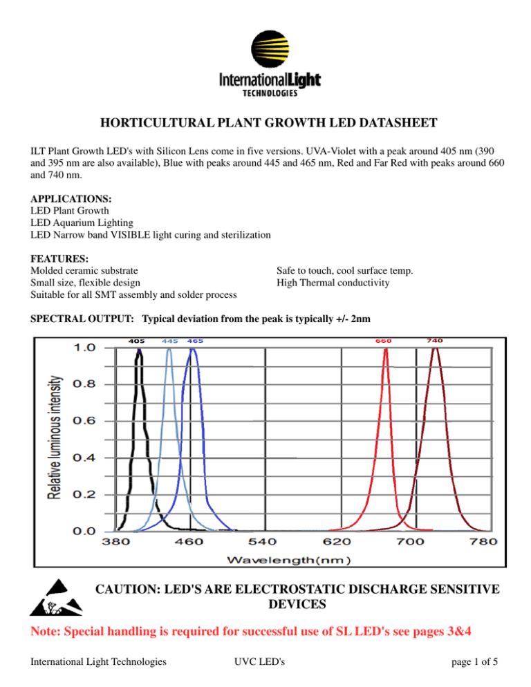
HORTICULTURAL PLANT GROWTH LED DATASHEET ILT Plant Growth LED's with Silicon Lens come in five versions. UVA-Violet with a peak around 405 nm (390 and 395 nm are also available), Blue with peaks around 445 and 465 nm, Red and Far Red with peaks around 660 and 740 nm. APPLICATIONS: LED Plant Growth LED Aquarium Lighting LED Narrow band VISIBLE light curing and sterilization FEATURES: Molded ceramic substrate Small size, flexible design Suitable for all SMT assembly and solder process Safe to touch, cool surface temp. High Thermal conductivity SPECTRAL OUTPUT: Typical deviation from the peak is typically +/- 2nm CAUTION: LED'S ARE ELECTROSTATIC DISCHARGE SENSITIVE DEVICES Note: Special handling is required for successful use of SL LED's see pages 3&4 International Light Technologies UVC LED's page 1 of 5 SPECIFICATIONS: Typical Characteristics of E405SL @Ta=250C, 350 mA FORWARD VOLTAGE OPTICAL POWER PEAK WAVELENGTH FWHM VIEW ANGLE MIN. 3.3 600 TYP. 3.4 680 MAX. 400 9 405 10 120 410 Maximum Ratings @Ta=250C UNITS V mW nm DEG Temperature of Aluminum PCB do not exceed 450 C 0 LUMINOUS FLUX OPTICAL POWER TYP. 13.3 18.3 870 FORWARD VOLTAGE 3.21 PEAK WAVELENGTH 440 445 VIEW ANGLE 130 Temperature of Aluminum PCB do not exceed 550 C MAX. TYP. 50 900 V DEG LUMINOUS FLUX OPTICAL POWER FORWARD VOLTAGE 3 PEAK WAVELENGTH 460 465 VIEW ANGLE 130 Temperature of Aluminum PCB do not exceed 550 C MAX. 3.8 470 UNITS lm mW V DEG MAX. 2.8 665 TYP. 0.4 450 UNITS lm mW V DEG LUMINOUS FLUX OPTICAL POWER FORWARD VOLTAGE 3 PEAK WAVELENGTH 740 50% POWER ANGLE 130 Temperature of Aluminum PCB do not exceed 550 C International Light Technologies MAX. 3.8 750 SOLDERING TEMP. 40Sec@180 0 C C 0 C 0 C INPUT POWER CURRENT REVERSE VOLTAGE OPERATING TEMP. STORAGE TEMP. SOLDERING TEMP. MAX. UNITS 3 800 max W mA 5 -20 to +65 0 to +40 40Sec@250 V C 0 C 0 C 0 POWER DISSIPATION CURRENT REVERSE VOLTAGE OPERATING TEMP. STORAGE TEMP. SOLDERING TEMP. MAX. 3 1000 max 5 -20 to +65 0 to +40 40Sec@260 UNITS W mA V 0 C 0 C 0 C Maximum Ratings @Ta =250C Typical Characteristics of E740SL @Ta =250C, 700 mA MIN. 0.2 0 Maximum Ratings @Ta =250C Typical Characteristics of E660SL @Ta =250C, 700 mA MIN. TYP. LUMINOUS FLUX 23.5 39 OPTICAL POWER 550 FORWARD VOLTAGE 2.2 PEAK WAVELENGTH 655 50% POWER ANGLE 130 Temperature of Aluminum PCB do not exceed 550 C 115 -20 to +45 -40 to +80 UNITS Typical Characteristics of E460SL @Ta =250C, 700 mA MIN. 45 JUNTION TEMP. OPERATING TEMP. STORAGE TEMP. Maximum Ratings @Ta=25 C lm mW 3.6 UNITS W mA 0 Typical Characteristics of E445SL @Ta=25 C, 700mA MIN. INPUT POWER CURRENT MAX. 1.2 700 max POWER DISSIPATION CURRENT REVERSE VOLTAGE OPERATING TEMP. STORAGE TEMP. SOLDERING TEMP. MAX. 3 800 max 5 -20 to +65 0 to +40 40Sec@260 UNITS W mA V 0 C 0 C 0 C Maximum Ratings @Ta =250C UNITS lm mW V DEG UVC LED's POWER DISSIPATION CURRENT REVERSE VOLTAGE OPERATING TEMP. STORAGE TEMP. SOLDERING TEMP. MAX. 3 1000 max 5 -20 to +65 0 to +40 40Sec@260 UNITS W mA V 0 C 0 C 0 C page 2 of 5 DIMENSIONS: 3.45 L x 3.45 W x 1.9 H, PCB .5 Silicon top 1.4 mm LIGHT DISTRIBUTION: See Graph Effective vertical emission distance: 1-3cm, Center of the emission area is center of the package. SOLDERING: UV LED'S ARE DESIGNED FOR REFLOW SOLDERING. See warnings below International Light Technologies UVC LED's page 3 of 5 SOLDERING WARNINGS: 1. Wave peak and soak-stannum soldering etc. is not suitable for this products. 2. Reflow soldering should not be done more than once. 3. The peak reflow temperature is 180 +10 , do not exceed 40 seconds 4. Repair should not be performed after the LEDs have been soldered. When repair is unavoidable, suitable tools are required. 5. Do not put stress on the LEDs during heating. 6. Do not warp the LED. 7. Do not stack PCBS or assemblies-Nothing should rest on the LED lens. Using Heat table to mount LED onto PCB. 1. Use syringe to apply tin onto the solder pad of the PCB. 2. Use tweezers to carefully place the LED onto to tin on the solder pad. 3. Place the mounted PCB/LED onto heat plate at proper temperature to warm tin (Note: in example tin melt occurs at 237 and we have set heat to 250) 4. Allow tin to melt (5-10 seconds only) Use caution: Over heating will cause PCB to oxidize. 5. Carefully remove from heat using tweezers and allow to cool slowly. HEAT DISSIPATION: UV LED SHOULD BE MOUNTED ONTO A HEATSINK TO PREVENT DAMAGE. The UV LED's mounted on aluminum metal-core printed circuit boards can be lighted directly, but we do not recommend this. Lighting the high power products for more than a few seconds without the appropriate heat International Light Technologies UVC LED's page 4 of 5 dissipation equipment can cause permanent damage. STORAGE: LED's should be stored in dry location, in a sealed package, with a desiccant. The storage temperature is best at 0 to 40 with a maximum of 60% humidity. HANDLING: 1. Soldering should be done right after opening the package (or within 24Hrs). If the package has been opened longer than 1 week or if the desiccants has changed color, components should be dried for 10-12 Hrs at 60± 5 . 2. Avoid rapid cooling after soldering. 3. Avoid mechanical force, shock and excess vibration during cooling process 4. This device should not be used in any fluid such as water, oil, organic solvent etc. If washing is required isopropyl alcohol should be used. 5. Components should not be mounted on warped PCB. 6. Do not use metal suction nozzle. Rubber or silica gel suction nozzle is recommended. 7. Avoid touching Lens, especially with sharp metal tools such as tweezers. 8. Do not apply pressure diagonally on the silicone lens. 1000g impact will cause fatal damage. 9. Do not cover the silicone resin of the LEDs with other resin. 10 A 2 cm clearance between stacks of PCBs or assemblies containing the LEDs is recommended so that nothing abrades or rests on the LED lens. Force applied to the LED resin will damage LED. CONTACT INFORMATION: International Light Technologies, 10 Technology Drive, Peabody MA 01960 Telephone: 978 818 6180, Fax: 978 818 6181, Website: www. intl-lighttech.com, Email: ilsales@intl-lighttech.com International Light Technologies UVC LED's page 5 of 5


