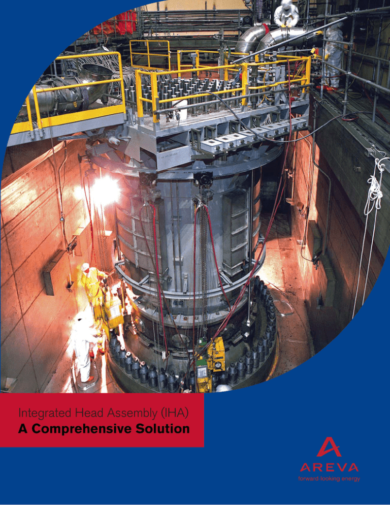
Integrated Head Assembly (IHA)
A Comprehensive Solution
Innovative best practices.
Dependable performance.
Proven success — reductions of six critical path days.
What is the IHA?
It is the future. The focus of AREVA’s Integrated Head Assembly (IHA) is to extend the life
of our customers’ plants with safe, reliable, innovative and efficient methods. Proven in the
industry time and time again to improve safety, reduce duration of refueling outages, and
lower personnel dose, this is one system enhancement you don’t want to overlook. The
IHA, fabricated and installed by AREVA, is customized to serve the unique requirements
of each and every plant in the U.S. and internationally — Combustion Engineering (CE),
Westinghouse and B&W designs. Invest in your future with a simple yet innovative upgrade
to your service structure with AREVA’s IHA.
Why is the IHA so important for the success of your plant?
Our customers can safely and efficiently improve performance and reduce outage durations
by installing AREVA’s IHA. A typical IHA can reduce polar crane use by a factor of ten.
In fact, we had a world record replacement outage at Salem in 2005. Our IHA has also
received a Top Industry Practice award. The design replaces the existing components
above the Reactor Vessel Closure Head (RVCH) to enable the entire RVCH to be removed
during a refueling outage in far fewer steps than the current design requires. It reduces
critical path time, maintenance costs and manpower by combining the RVCH and the
majority of its supporting systems into a single removable unit.
Our customers have captured reductions of up to six critical path days — thus, critical
outage resources can be made available to potentially decrease total outage duration
even further. Easy installation features and 360° inspection access to Control Rod Drive
Mechanism (CRDM) penetrations enable you to compress outage schedules and get your
plant reconnected to the grid in a shorter period of time.
Developed with strong customer input, our IHA design addresses the main barriers to upper
head maintenance that utilities may experience.
Features
• New Integrated Missile Shield
• Head Area Cable System
• Head Lifting Frame
• Cable Bridges
• IHA Seismic Support System
• Reactor Head Vent-Piping
• CRDM Cooling System
• Shielding and Work Access
Reliable experience.
The AREVA IHA design incorporates the experience and knowledge gained while performing
refueling services for Westinghouse, B&W and CE operating plants. Our demonstrated
performance in over 75 RVCH replacement projects worldwide and our continuous, active
supply of NSSS components provides a solid foundation to make your IHA project a success.
2
Feature details.
AREVA provides customized IHA products allowing you
to choose the IHA features to maximize your return.
New Integrated Missile Shield
CRDM Cooling System
Our IHA integrates the CRDM shield into the upper
reactor vessel head assembly, eliminating the need
for heavy concrete/steel missile shields that must
be removed and take up valuable storage space
in containment. The design of the missile shield is
NSSS-design specific and depends on the CRDM
maintenance requirements. In IHAs for some reactors,
the missile shield will be an integral part of the lifting
system. For others, it will be an integral part of the
working platform. The IHA missile shield is designed to
meet the requirements of the USNRC Standard Review
Plan Section 3.5.2. Since it is positioned above the
CRDMs as part of the assembly, there is no need to
disassemble or remove the missile shield in order to lift
the closure head.
The IHA cooling system is self-contained in the
reactor vessel head assembly, minimizing ductwork
and piping. A compact integral set of ducts and fans
cool the rod drives and the rod drive nozzles. Cool
air is drawn from the side of the shroud inside the air
baffle surrounding the rod drives and the hot air is
discharged into a plenum through a set of ducts in the
annulus region of the IHA. The cooling fans are directly
connected to the plenum to discharge the hot air from
the plenum into containment or, if required, can be
directed into the existing containment cooling system.
The rod drive cooling system in the IHA includes at
least one cooling fan as a backup.
Head Lifting Frame
Since the IHA Head Lifting Frame is permanently
mounted, attachment and removal operations for the
tripod are eliminated and valuable lay down space
is conserved. The lifting frame consists of lift rods,
shackle, clevises and pins. The design of an integrated
tripod for the IHA lifting system is plant-specific and
depends on the available space in the refuel cavity,
RVCH travel path, and reactor head stand area. The
IHA lifting system is designed to meet the requirements
of ANSI N14.6 and of the USNRC NUREG 0612.
IHA Seismic Support System
The IHA seismic support system includes a supporting
mechanism for individual rod drives and another
supporting mechanism for the IHA components. The
rod drive supporting mechanism transmits seismic
loads from the individual CRDMs to the IHA supporting
mechanism. The IHA supporting mechanism transmits
the seismic loads from the individual rod drives as well
as from the individual IHA components either to the
reactor cavity walls or to the reactor head depending
on the original NSSS design. The seismic loads that
are transmitted to the reactor cavity walls are through
the seismic tie-rods that are connected between the
IHA and the reactor cavity walls. The seismic loads
that are transmitted to the reactor head are through
the supporting structure of the IHA. The IHA seismic
support system does not alter the existing seismic load
path. These load paths can be upgraded if required.
3
Head Area Cable System
A set of quick-connect couplings for the head area
cable system reduces the outage time required to
disconnect or connect cables from the rod drives.
Cabling is disconnected only at easily accessible
connector plates mounted along the circumference
of the IHA. Cables inside the IHA remain with the IHA
during lifting and storage. All head area cables are
routed along the messenger wires that are installed
inside the IHA and above the top of the rod drive
pressure housings to provide permanent supports to
the head area cables. If required, the rod drive cables
are routed to meet IEEE separation criteria for IEEE
Class 1E cables. All head area cables are supported
along the messenger wires to the plant-specific seismic
requirements. The messenger wires are designed to
provide minimum disruption to the CRDM pressure
housing removal process, if required.
Cable Bridges
Cable bridges support the cable bundles between the
IHA connector plates and the primary shield walls. The
cable bridges can be swung upward in order for the
IHA to be lifted free of the reactor vessel. These cable
bridges eliminate the need to remove and install cables
or cable trays and protect the cables and connectors
from damage. Cable bridges are designed to the plantspecific seismic requirements.
Shield doors open, revealing insulation and the access
ports removed from insulation for visual and robotic
penetration inspection.
Feature highlights
• Integrated missile shield
Reactor Head Vent-Piping
The IHA simplifies access to the head vent-piping
interface by routing it inside the IHA and locating the
disconnect/reconnect access on the same elevation
as the connector plates. The head vent-piping can
be disconnected at the interface flange on the
connector plate level prior to removing the IHA from
the reactor vessel.
Shielding and Work Access
The IHA includes integral shielding in critical areas to
minimize exposure during refueling activities such as
tensioning/detensioning. The integral stud-tensioner
monorail eases tool-handling effort. Work platforms,
ladders and removable access panels or doors are
incorporated into the design to facilitate maintenance
and inspection requirements. The modular, bolted
design accommodates disassembly/reassembly
without welding or cutting, in case of an extraordinary
maintenance event.
• Improvements to head vent routing
& connections
• Integrated shielded work platform
• Integrated fans & ductwork
• Improvements to CCW line connections
• Integrated shielding around lower shroud
• Removable RVCH penetration inspection ports
in insulation package
Summary of benefits
• Reduction of up to six critical path outage days
• Design addresses main barriers to reduced
outage schedules
• Dose reduction of three-to-four person REM
per outage
• AREVA’s IHA design achieves the lowest
personnel exposure in the industry for an
RVCH replacement
• IHA installation performed within a normal
refueling outage schedule
• Safety design reduces potential for personnel
injury & promotes zero OSHA recordables
4
Reduced dose. Enhanced safety.
Quick response and fast service —
without compromising safety.
Reduced safety hazards
+ reduced dose = reduced stress
AREVA’s IHA is designed with safety in mind.
Numerous safety features are built into AREVA’s
IHA to reduce the potential for personnel injury and
to promote zero OSHA recordable accidents. For
instance, the IHA incorporates the missile shield,
eliminating six heavy lifts. The current CRDM
cooling ductwork is eliminated, greatly increasing
the safety margin for reactor-head disassembly/
reassembly activities. Virtually all work associated with
disconnecting systems from the RVCH is performed
from the refueling floor or walkways on the IHA —
eliminating the need for a safety harness. In addition,
the lower shroud is shielded, eliminating the need for
the transfer and installation of lead shielding while the
reactor vessel head is in the refuel canal. Handrails
are included around the service platform and folding
batwings. Features such as these contribute to an
outage dose reduction, increasing the safety margin
for workers.
Our IHA design offers the potential for dose reduction
between three to four REM per outage. Part of the
design — the radiation shield surrounding the CRDM
nozzles — replaces the need for temporary shielding
around the lower shroud.
Key safety features of the IHA
• Cables uniformly routed along specified paths and
contained in cable trays to prevent tripping hazards.
• Retractable cable bridges reinforced to support
personnel load.
• A hoist rail system allows for easy installation of
trolleys without a manbasket or work platform.
• Moveable radiation shielding around
lower shroud eliminates temporary
shielding installation.
• Removable RVCH insulation ports for faster, safer
penetration inspection.
5
Superior design. Positive results.
Our design, fabrication and installation
experience provides you with the
confidence of skilled expertise and the
reassurance of dependable service.
AREVA also offers the following
services in conjunction with the IHA:
Our IHA design eases access to vital reactor vessel
head components and lowers maintenance time.
A CRDM cooling system, head area cable system,
reactor head vent-piping and integral work platforms,
ladders and removable access panels are all
incorporated into the IHA. And with cooling system
and cable routing improvements, an easy cable
connect/disconnect feature, minimized use of the
polar crane, an innovative head-lifting frame, tailormade cable bridges, and an optimal lay-down space,
we can complete the IHA installation efficiently and
reduce personnel resources and man-hours normally
needed for a project of this scope.
• Mechanical and electrical engineering analyses
• Total integrated outage services, including
component installations design change packages
• Fans, chillers, vent lines and valves,
spare components
• Head area cable sets and bulkheads
• RVCH Insulation with access ports for visual and
robotic inspections
• Permanent reactor cavity seal plates
• Self-contained rod drive cooling system to
minimize ductwork and piping
• Simplified access to head vent-piping interface
• IHA replacement available as part of overall head
replacement package
6
AREVA provides its customers with
solutions for low-carbon power generation
in North America and all over the world.
As the leader in nuclear energy and a significant,
growing player in the renewable energies sector, AREVA
combines U.S. and Canadian leadership, access to
worldwide expertise and a proven track record of performance.
Sustainable development is a core component of AREVA’s
strategy.
Its nearly 5,000 U.S. and Canadian employees work every day to
make AREVA a responsible industrial player helping to supply
ever cleaner, safer and more economical energy to the greatest
number of people.
For more information, contact your AREVA VP, Key Accounts – AREVA Inc. – 7207 IBM Drive, Charlotte, NC 28262
Tel: 704 805 2410 – Fax: 434 832 5629 – www.us.areva.com
The data contained herein are solely for your information and
are not to be construed as a warranty or other contractual obligation.
©2013 AREVA Inc. All rights reserved.
ANP:U-232-V2-13-ENG
Energy is our future, don’t waste it!
www.areva.com


